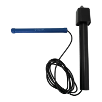
B. Observe that the yellow “DETECT” LED turns ON and the green “XMIT” LED is blinking for 1 second. (Shown in Step 3B.) This LED
sequence indicates that the Vehicle Sensor has detected the metal and is transmitting.
4. INSTALLING YOUR WIRELESS VEHICLE SENSOR PROBE AND CONTROL BOARD
(REMOVE THE (2) C SIZE BATTERIES FOR THIS STEP):
PLAN YOUR INSTALLATION LOCATION FOR THE BEST RADIO FREQUENCY RANGE
A. Make sure your gate is in the CLOSED POSITION and opener is OFF to avoid accidental opening of the gate.
B. Complete steps 1–3 as shown previously.
C. Measure and lay the sensor probe on the ground, next to driveway, and at least 20 feet from the open edge of the gate. We recommend
placing sensor probe closest to side of driveway that vehicle exits. Prop up the PVC Pipe that holds the Control Board at least 6"
above ground.
D. INSTALL C BATTERIES INTO THE BACKSIDE OF THE CONTROL BOARD and wait for the LEDs to stop blinking before continuing.
E. Make sure there are no vehicles or steel or metal objects near the sensor probe. Turn the gate opener system on.
F. Move a steel object over the sensor probe (repeating Step 3A)
OR press and quickly release the push button on the Vehicle Sensor
Control Board to send the “OPEN” signal to the gate.
G. The green “XMIT” LED on the Vehicle Control Board will start blinking rapidly and the yellow “DETECT” LED will stay lit for 1 second to
indicate that the “OPEN” signal is being sent.
H. The gate should open when it receives the signal from the wireless vehicle sensor.
I. Once the desired location is located,
REMOVE THE BATTERIES FROM THE BACKSIDE OF THE CONTROL BOARD
BEFORE PROCEEDING.
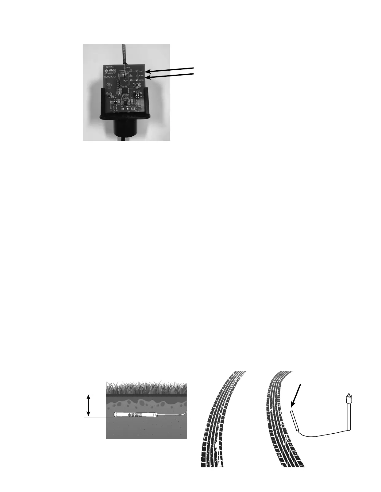
DIG A TRENCH FOR THE SENSOR PROBE AND WIRE:
A. Dig a trench approximately 12" deep to bury the Sensor Probe. In most cases, the sensor should lie in trench horizontally and parallel to
the driveway.
B. Dig a trench to bury the wire between the Sensor Probe and the PVC Pipe that holds the Control Board and Batteries.
Detect LED
Step 3B
XMIT LED
Dig trench
approximately
12 inches deep and
parallel to ground
surface
Parallel to driveway
 Loading...