5 6
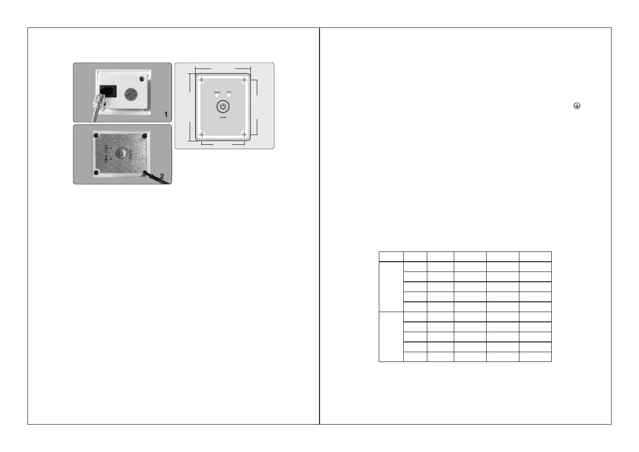
2). Assemble the remote control box
54 mm
66 mm
52 .5mm
41 mm
1) Fixed on the plane with an opening, four screws can be fixed directly on the four
mounting holes of the remote control box.
2) Connect the remote control cable between the box and the inverter.
5. BATTERY
1. The battery is designed to supply the inverter with DC input voltage and the rated
voltage should be in accordance with the rated input voltage of the inverter. Any
voltage exceeding the range of the input voltage of the inverter will cause the inverter
to go into overload and could possibly damage the inverter. The battery should
supply enough current for the load. The load is the amp or watt rating of the
equipment being powered by the inverter. A small capacity battery cannot provide
enough power for a large electrical equipment. In this case, the battery will cause the
inverter to go into under voltage protection because of the load put on the battery. A
simple way to calculate the load or amps required from your battery is to divide watts
of equipment by battery voltage. Due to the consumption of the inverter itself, the
actual current will be about 10%. For example, the voltage of lead acid battery is
12VDC, and load of the equipment is 1000W, therefore, the actual current needed
from the battery is about 1000W / 12V = 83.3 amps per hour. Add 10% for efficiency
loss and you get 83.3 * 110% = 91.6 amp per hour needed. If you don't know the
wattage of your equipment, you can figure the wattage by multiplying AC amps by AC
voltage. For example, a refrigerator is 8 AC amps * 120 Volts AC = 960 watts.
Remember, all equipment has a start-up requirement 3-5x its running wattage. In this
example, 960 watts * 3 = 2880 watts needed from the inverter so don't size your
inverter too small.
2. Battery operating time
The battery operation time depends on battery capacity and load. The formula for
operating time is: battery capacity divided by the value of the load divided by battery
voltage times 110%. For example, using the numbers from above, the batter
specification is 12V, 200Ah capacity and the load is 1000W. Take battery capacity
200Ah / 91.6 amps = 2.18 hours of run time if you fully deplete the battery. This is
NOT recommended. Deep cycle batteries last longer when they are only depleted to
50% of capacity.
6. CONNECTION
1) Grounding
The power inverter has a terminal on the rear panel marked " Grounding "or " ".
This is used to connect the chassis of the power inverter to ground. The ground
terminal has already been connected to the ground wire of the AC output receptacle
through the inverter.
The ground terminal suggested be connected to the ground wire, which will vary
depending on where the power inverter is installed. In a vehicle, connect the ground
terminal to the chassis of the vehicle. In a boat, connect it to the boat’s ground
system. In a fixed location, connect the ground terminal to earth.
2) Battery terminals
Before you connect the battery cables, make sure the power switch is in the off
position. Connect Red (+) battery cable to Red (+) inverter terminal. Connect Black (-
) battery cable to Black (-) inverter terminal. Connect Red (+) battery cable to Red (+)
battery terminal. Connect Black (-) battery cable to Black (-) battery terminal.
Alligator clamp cables may be used but only to connect to the battery. Do not use
clamps on inverter terminals. Alligator clamps are not a permanent solution. You may
see a spark during connection. Do not reverse the polarity. This may damage the
inverter and void warranty.
Cross-sectional cable must be thick enough to avoid too much voltage drop . Refer to
below table to choose cables.
Rate d vo lt age
of inv er te r
Curr en t ma x.
load p ow er
Max. c ur re nt
of wir e
Spec if ic ation of
wire l en gth≤1m
Spec if ic ation of
wire l en gth≤1m
Spec if ic ation of
wire l en gth≤N m
1200W
1500W
2000W
2500W
3000W
1200W
1500W
2000W
2500W
3000W
12V
6AWG
(13.3mm )
2
4AWG
(21.15mm )
2
3AWG
(26.67mm )
2
2AWG
(33.62mm )
2
1AWG
(42.41mm )
2
N×6AWG
(N×13.3mm
2
)
N×4AWG
(N×21.15mm
2
)
N×3AWG
(N×26.67mm
2
)
N×2AWG
(N×33.62mm
2
)
N×1AWG
(N×42.41mm
2
)
3AWG
(26.67mm
2
)
1AWG
(42.41mm
2
)
0AWG
(53.49mm
2
)
00AWG
(67.43mm
2
)
000AWG
2
(85.01mm )
24V
100A
150A
200A
250A
300A
50A
75A
100A
125A
150A
9AWG
(6.63mm )
2
7AWG
(10.55mm )
2
6AWG
(13.3mm )
2
5AWG
(16.77mm )
2
4AWG
(21.15mm )
2
N×9AWG
(N×6.63mm
2
)
N×7AWG
(N×10.55mm
2
)
N×6AWG
(N×13.3mm
2
)
N×5AWG
(N×16.77mm
2
)
N×4AWG
(N×21.15mm
2
)
6AWG
(13.3mm
2
)
4AWG
(21.15mm
2
)
3AWG
(26.67mm
2
)
2AWG
(33.62mm
2
)
1AWG
(42.41mm
2
)
 Loading...