REPAIR INSTRUCTIONS - MP SERIES
9
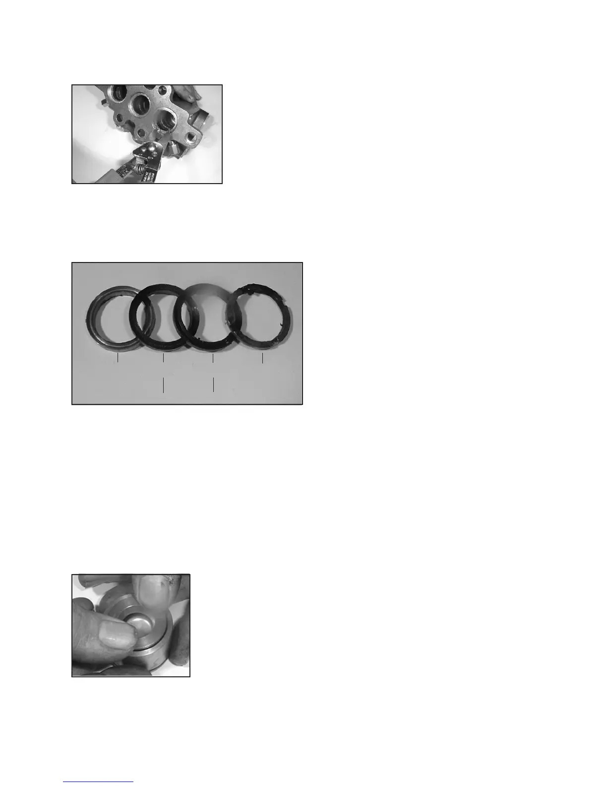
39 40 41 41A
(40A in MP4135W) (40 in MP4135W)
15. Replace the rear support ring (#35A for MP4120W/MP4124W and
#41 for MP4130W/MP4135W). Replace the rear v-sleeve (#35B for
MP4120W/MP4124W and #40 for MP4130W/MP4135W) and rear
pressure ring (#35C for MP4120W/MP4124W and #39 for MP4130W/
MP4135W) making sure that the grooved side is facing the discharge
end of the manifold (#43). For MP4120W/MP4124W, replace the rear
o-ring (#35D) into the back of the manifold (#43). Replace the snap
ring (#36).
16. Reinstall the pressure ring (#39), v-sleeve (#40 /
#40A fpr MP4135W), support ring (#41 / #40 for
MP4135W) and intermediate ring (#41A) into each
plunger bore. Re-install the tension spring (#42).
For MP4120W/MP4124W only replace the spacer
ring (#52A).
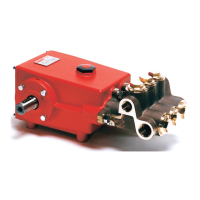
17. Reassemble the inlet valve assembly in the reverse order of step #6. Make certain all the components
are press t together and that the spring retainer (#54) is slightly counter sunk in the valve housing (#52).
Grease the o-ring (#53) and replace it on to the valve housing. Reinstall the entire inlet valve assembly
into the manifold (#43). Replace the tension plugs (#42A) and tighten.
18. Reassemble the discharge valve assembly by placing the valve plate (#45),
spring (#46), and spring retainer (#47) on top of the valve seat (#44). Press
t together. Place the entire discharge assembly into discharge port making
certain the assembly is properly seated. Replace discharge plug (#48) and
tighten securely.
19. Again lubricate the plungers (29B) and slide the manifold (#43) gently and
evenly over the plungers. Press the manifold rmly into place against the
crankcase (#1). Replace the spring washer (#50A) and tighten the manifold
stud nuts (#50) to 700 inch-pounds (79 Nm).
 Loading...