10
INSTALLATION INSTRUCTIONS
To protect from excessive pressure and/or tempera-
ture, the manufacturer has installed a temperature and
pressure-relief valve that meets the requirements of
the Standard for Relief Valves and Automatic Gas
Shut-Off Devices for Hot Water Supply Systems,
CSA 4.4, in Canada and ANSI Z21.22, in the United
States. This relief valve has a maximum set pres-
sure that does not exceed the hydrostatic working
pressure of the water heater (150 psi = 1,035 kPa) and
a BTU/h rating equal to or greater than the input rating,
as shown on the water heater rating plate. It should never
be plugged or removed from the opening marked for it on
the water heater.
If this relief valve should need to be replaced, use only
a new temperature and pressure-relief valve. Never
install an old or existing relief valve, as it may be
damaged or inadequate for the working requirements of
the new water heater. This new relief valve must meet
all local codes or, at a minimum, the requirements listed
above. Never install any other type of valve between the
relief valve and the water heater.
A discharge line must be installed into the relief valve.
The discharge line:
• Mustnotbesmallerthantheoutletpipesizeofthe
relief valve.
• Must not terminate less than six (6) inches (15.2
cm) and not more than twelve (12) inches (30.5 cm)
above a floor drain.
• Mustnotberestrictedinanyway.Donotthread,cap
or in any way restrict the end of this outlet.
• Mustbeofamaterialcapableofwithstanding210
o
F
(99
o
C) without distortion.
• Mustbeinstalledtoallowcompletedrainageofthe
relief valve and discharge line.
• Mustterminateatanadequatefree-flowingdrain.
Pressure Build-up in a Water System
When the water heater operates, the heated water
expands creating a pressure build-up. This is a
natural function and is one of the reasons for installing a
temperature and pressure-relief valve. If the cold water
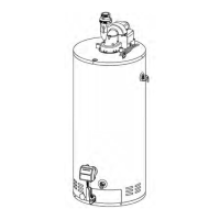
Figure 11
1) Vent pipe
2) Power vent assembly
3) Union
4) Cold water
manual shut-off valve
5) Cold water inlet
6) Expansion tank
7) Temperature
and pressure-relief valve
8) Overflow tube
9) Drain valve
10) Combustion
air intake holes
11) Drain pan
12) Free-flowing floor drain
13) Sight glass
14) Resettable Thermal Switch
15) Outer access door
16) Inner access door
17) Flammable vapour sensor
18) Cap
19) Drip leg (Sediment trap)
20) Gas supply
manual shut-off valve
21) Union
22) Gas control valve
23) Rating plate
24) Dip-tube
25) 12’ Power cord (3,86 m)
26) Hot water outlet
27) Union
28) Flame sensor
29) Ignitor
30) Burner orifice
31) Burner
2
5
6
3
4
7
8
24
9
10
11
16
14
15
13
12
21
17
18
20
19
22
23
25
27
26
31
29
28
30
1
Minimum Slope
1/4”/foot (21mm/m)
 Loading...