32 33
BA24
BA24
UK UK
BA24 / AS06300
Electronic control unit for the automation of one
or two motors – 24V dc – for swinging and sliding gates,
overhead garage doors and barriers
230Vac monophase 50/60 Hz
1 or 2
24 Vdc
24Vdc 10W max
24Vdc 3W max
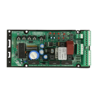
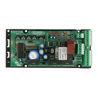
Control unit
Type
Power supply
N° motors
Motor power supply
Flashing light
Warning light
24Vdc 8W max including safety device power supply
Accessories power supply
24Vcc 8W max including accessories power supply
-20°C +60°C
Plug-in
Safety device power supply
Operating temperature
Radio receiver
TECHNICAL SPECIFICATIONS / FUNCTIONS
• Red warning LEDs of N.C. contacts. There isn't the safety devices LED. See “SIGNALLING LED” table.
• Green warning LEDs of N.A. contacts. See “SIGNALLING LED” table.
• Two electrical locks management.
• Safety test run before the opening and closing movement.
• Photocell 1 test run before the opening and closing movement.
• Amperometric circuit test run before the opening and closing movement.
• Stop and motion inversion for 2 seconds after intervention of the safety devices. At the next START pulse the
motion reSTARTs in the obstacle freeing direction.
• SEPARATE SAFETY DEVICES POWER SUPPLY. Connect the safety devices that must be tested to this
clamp.
• Digital programming of all functions.
• Working time settable independently in opening and closing for each motor.
• Deceleration time settable independently in opening and closing for each motor in the ending motion phase
(soft-stop).
• Gate phase shift time settable independently in opening and closing.
• Settable pedestrian working time.
• Pause time settable and differentiated for complete opening or pedestrian opening.
• Thrust force settable on 10 levels for each motor.
• Decelerations selectable and settable independently on 10 levels for each motor.
• Decelerated departure (soft START) that can be selected in 3 different modes.
• Absorption (anti-crushing) control settable on 100 levels for each motor both in thrust phase and in
deceleration phase.
• Deceleration enabling: with single or double limit switches reading.
• 4 possible working functions (step-by-step, step-by-step with stop, co-ownership's or automatic, dead-man).
• Possibility to choose the equipment configuration among swinging, overhead/barrier and sliding, single or
double.
• SAFETY DEVICE choice with N.C. contact or 8K2 resistive.
• Anti-crushing enabling (motion inversion for 2 seconds and stop) or amperometric detection for limit switch.
INSTALLATION
INSTALLATION WARNINGS
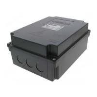
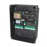
Use cable glands that can assure the correct mechanical connection of the wiring and maintain the IP55
protection degree of the box (2).
• Before the installation, fit a magnetothermal or differential switch with a maximum capacity of 10A upstream of
the system. The switch must guarantee omnipolar separation of the contacts with an opening distance of at
least 3 mm.
• To prevent possible interference, differentiate the power cables and always keep them separate (minimum
cross-section 1.5 mm²) from the signal cables (minimum cross-section 0.5 mm²).
• Make the connections referring to the following tables and to the attached screen-print. Be extremely careful to
connect in series all the devices that are connected to the same N.C. (normally closed) input, and in parallel all
the devices that share the same N.O. (normally open) input. Incorrect installation or improper use of the
product may compromise system safety.
• Keep all the materials contained in the packaging away from children, since they pose a potential risk.
• The manufacturer declines all responsibility for improper functioning of the automated device if the original
components and accessories suitable for the specific application are not used.
• After installation, always check carefully proper functioning of the system and the devices used.
• This instruction manual addresses persons qualified for installation of “live equipment”. Therefore, good
technical knowledge and professional practice in compliance with the regulations in force are required.
• Maintenance must be carried out by qualified personnel.
• Before carrying out any cleaning or maintenance operation, disconnect the control unit from the mains.
• This control unit may only be used for the purpose for which it was designed. Check the aim of the final use
and make sure that all safety measures are taken.
• Use of the product for purposes different from the intended use has not been tested by the manufacturer,
therefore any work is carried out on full responsibility of the installer.
• Mark the automated device with visible warning plates.
• Warn the user that children or animals may not play or stand around near the gate.
• Appropriately protect the danger points (for example, using a sensitive frame).
• The control board alone will not ensure safety against crushing. Make sure that the safety devices connected
to the control board are appropriate for the purpose.
• Possibility to program: automatic closing, fast closing, pre-flashing, hammer stroke, final closing and opening
stroke, courtesy light, ending movement additional time, flashing light (both flashing and fixed), external watch
management with three different modalities, number of cycles for scheduled maintenance, installer code and
number of performed cycles and power supply days.
 Loading...