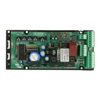
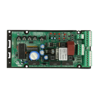
LOGIC CARTE
allows programming all the functions of the control unit excluding
the operating time of the operators, which has already been stored
in the microprocessor which controls the functioning logic.
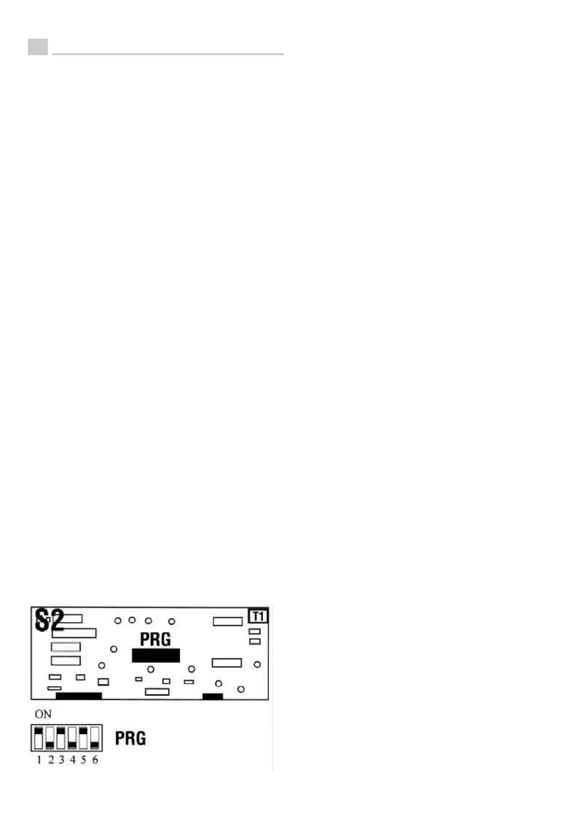
Switch 1: if in the OFF position, a delay of 5 seconds is set for
closing of motor 1 to prevent wing overlap. If in the ON position
this delay is cut out, thus the two motors will start simultaneously.
If only one motor is used the switch must be in the ON position.
Switch 2: (only operational if switch 4 is ON). If in the OFF position,
a pause time of 1 minute is set before automatic closing. If in the
ON position a pause time of 30 seconds is set.
Switch 3: If in the OFF position, the photocell is enabled for
functioning only during closing. If in the ON position, the photocell
is enabled during both opening and closing.
Switch 4: If in the OFF position, automatic closing is cut out (the
gate only closes by sending a pulse from the button or the radio
control). If in the ON position, automatic closing is enabled, and
the gate closes after the time set on the switch 2, or by sending a
pulse from the button or the radio control if the switch 5 is in the
OFF position.
Switch 5: If in the OFF position, the sequential open-stop-close
and vice versa functioning logic is enabled. If in the ON position
the step button (N) executes opening only; closing is automatic.
Switch 6: If 2 motors are used, it must be in the OFF position. If
only one motor is used, it must be in the ON position.
Regulators:
T1 TRIMMER for regulation of the maximum force of the operators.
Turning clockwise increases the force, anticlockwise decreases it.
Fuses:
F1 F3.15A fuse to protect the entire power supply 220-230V
50-60Hz
F2 F10A fuse to protect the 12V battery
F3 F5A fuse to protect 12VDC output of the control unit.
LEDs FOR FUNCTIONAL CONTROL
L1 - Red LED - Photocell: on when the photocell is powered and
aligned; off when the photocell is intercepted or not aligned or
powered.
L2 - Red LED - Stop button: on when the button is not pushed
(contact closed), off when the stop button is pushed or when not
connected. If this LED is off, the control unit does not perform any
function.
L3 - Green LED - Start button: on only when a pulse from the radio
control or the step button arrives (terminal 19).
S1 Radio receiver card: if the 10 dip switches for code
programming are present, set the same sequence as set on the
transmitter. If the 10 dip switches are absent the radio receiver is
self-learning and thus the instructions at the end of this handbook
must be followed.
TECHNICAL CHARACTERISTICS
The control unit can function with mains power of 220-230 V 50-
60 Hz and with a 12 VDC battery.
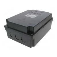
The 1.9/2.1 Ah buffer battery, which may be inserted in the control
unit container, is not required for good functioning of the gate, but
intervenes only in case of power failure to guarantee functioning
of the gate for 20 complete continuous cycles in perfect conditions.
Temperature range: -20 to +70 degrees C
Humidity: <95% without condensation
Power supply voltage: 220-230 V 50-60 Hz and 12 VDC
Maximum card absorption (excluding motors, lights and external
accessories): 70 mA
Micro power cut-offs (at max. load and min. voltage): 20 mS
Maximum power at each motor output: 70W 12 VDC
Max. load on warning light output: 3W 12 VDC
Max. load on flashing light output: 15W 12 VDC
Available current on photocell and accessories output: 1A 12VDC
All the inputs must be used as clean contacts, since power is
generated in the card and arranged to guarantee double or
reinforced insulation with respect to the live parts.
All inputs, both functional and safety, are controlled by a
programmable integrated circuit (PAL).
The stop input (terminal 20 - N.C. contact), other than resetting the
programmable integrated circuit, does not supply the relay coil if it
remains open; it can, therefore, be used to unconditionally lock the
motor in conditions of danger to the user.
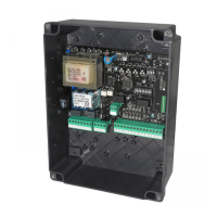
ELECTRICAL CONNECTIONS TO CONTROL UNIT
A/B) POWER SUPPLY 220-230V 50-60 Hz; connect to terminals 1
and 2.
C) Earth conductor; connect to terminal 3.
D) MOTOR 1 12 VDC; connect to terminals 4 and 5.
E) MOTOR 2 12 VDC; connect to terminals 6 and 7.
F) 12VDC output for connection of the buffer battery; connect the
negative pole (black) of the battery to terminal 8 and the positi-
ve pole (red) to terminal 9.
G) 12 VDC output for supply of photocells, etc.; connect the nega-
tive (-) to terminal 10 and the positive (+) to terminal 11.
H) 12 VDC output for connection of electrolock which functions
for 3 seconds at the beginning of the gate opening phase;
connect to terminals 12 and 13.
I) 12 VDC output for connection of the warning light to signal gate
open; connect to terminals 14 and 15.
L) 12 VDC flashing light; connect to terminals 16 and 17.
M) Common wire of buttons and photocells; terminal 18.
N) N.O. contact of button for control of sequential open-stop-close
and viceversa, or open only, positioning the switch 5 of the PRG
programmer to the ON position; connect to terminals 18 and
19.
O) N.C. contact of stop button; connect to terminals 18 and 20.
P) N.C. contact of photocell safety device; connect to terminals 18
and 21.
SAFETY AND SIGNALLING DEVICES
Photocell: The functioning of the photocell varies depending on
the position of switch 3 on the PRG programmer. When the switch
3 is in the OFF position, the photocell stops the gate only if in the
closing phase, inverting the motion only when it is freed. When the
switch 3 is in the ON position the photocell stops the gate both in
the opening and closing phase. The gate restarts opening only
when the photocell is freed.
Safety frame: The N.C. contacts of the safety frame must be
connected in series to the N.C. stop contact at terminal 20; if the
frame is intercepted, the opening or closing motion of the gate is
stopped.
Force regulator: The control unit is fitted with a device which may
be adjusted through the trimmer T1, which allows calibrating the
maximum force available to the operator. If the gate is slowed
down due to an obstruction, the wing of the relevant gate stops,
both in the closing and opening phase. This anti-crushing and
anti-entrainment device guarantees safety in the entire area
occupied by the gate during movement. Therefore it is important
to make the adjustment carefully so that a maximum force of 15 kg
(UNI 8612) is obtained on the extreme point of the wing.
Warning light: It comes on when the gate opening phase begins
and remains on as long as the gate is open (gate stays open without
using the stop button); at the beginning of the closing phase it
goes off.
Flashing light: It comes on when a motor starts and goes off
when the last motor has stopped.
PROGRAMMING, REGULATING AND PROTECTION DEVICES
Programming:
8
UK
PRG: 6-switch programmer mounted on the logic card S2, which
 Loading...