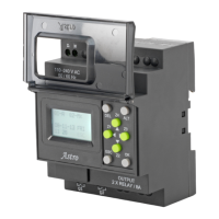
EasyManua.ls Logo

GIC Astro T2DDT0 - User Manual

GIC Astro T2DDT0
4 pages
Print Icon
To Next Page IconTo Next Page
Loading...
DIGITAL TIME SWITCH- Astro
RoHS
SAFETY NOTICE:
1. Only qualified persons are authorized to install the ASTRO.
2. Automation and control devices must be installed so that they are protected
against any risk of involuntary actuation.
3. It is essential to ensure that all control system connections meet applicable safety
standards.
4. Fluctuations or variations in the mains supply voltage should not exceed the
tolerance stated thresholds.
Astro” is an astronomical time switch specifically designed for lighting
applications. One can program the ASTRO to turn ON and turn OFF the light with
reference to the sunrise and sunset. R, Y, B inputs can be looped to address single
phase distribution or independently given to control 3 phase distributions. Relay
channels can be independently programmed for ON or OFF operation by specifying
the time offset with reference to sunrise and sunset or twilight rise and set.
CONNECTION DETAILS:
To connect Astro to PC using Serial or USB port: Astro has TTL Serial Port.
Use TTL to RS232 cable [GFDNN2S] or USB cable [GFDNN1] for communication
between Astro & PC.
To connect Astro in RS485 network: Use standard isolated RS232 to RS485
2W/4W converter with Automatic flow control to connect in RS485 network. Connect
TTL to RS232 cable [GFDNN2S] to the Astro.
Season Mode: During rainy season or in cloudy
atmosphere, sunlight may be insufficient. Hence
different time offset needs be programmed to control
light switching. User can program period of such
season and the related time-offset. This feature helps
switch lights early with respect to sun rise/set and
automatically move back to original settings after the
season period. To set this feature, refer page 3->
Screen tagged as ‘4’.
Day-light Saving Time (DST): DST is the period in
which clocks in certain countries are set one hour or
more ahead of standard time to effectively use natural
daylight. ASTRO provides settings to easily define DST
start and end months and DST offset time to
effectively manage the shifting of clock year after year
without any manual intervention. To set this feature,
refer page 3-> Screen tagged as ‘7’.
UV/OV Mode: When Under / Over Voltage condition
prevails, load can be tripped off thereby protecting
load from damage due to extreme voltage
irregularities. Users can set Under & Over Voltage as
per their requirement. To set this feature, refer page
3-> Screen tagged as ‘5’.
Modbus Communication: Three Phase version of
Astro supports Modbus RTU communication protocol
to read coil status, write or override coils, set season
periods etc. from SCADA software. Modbus related
information is mentioned on page 2. To set this
feature, refer page 3-> Screen tagged as ‘8’.
MANUAL OVERRIDE MODES:
By default and on the field, the device is generally in
“AUTO” mode shown on the screen as “Qn-A”. But, for
the purpose of maintenance or because of extremely
bad weather conditions for forceful switching, user has
an option of four different override modes for output
channel switching.
1. Manual OFF (T2DDT0): This override can be used
to turn off the output channel forcefully. Once this
override is selected, the output remains in OFF
condition forever unless user selects another mode.
This is valid even EUT is powered
OFF and ON. The
manual mode always overrides other operating mode.
Shown on screen as “Qn-M x”.
2. Manual ON (T2DDT0): This override can be used
to turn on the output channel forcefully. Once this
override is selected the output remains in ON condition
forever unless user selects another mode. This is valid
even EUT is powered OFF and ON. The manual mode
always overrides other operating mode. Shown on
screen as “Qn-M”.
3. Auto OFF (T2DDT0, T3DDT0): Used to turn OFF
the output channel forcefully. But the OFF condition will
not be forever. The device will automatically change the
operating mode from Auto OFF to AUTO on next auto
event. For example, user selects Auto OFF at 4:00 A.M.
and device has OFF event at 7:00 A.M. The EUT will
switch OFF from 4:00 A.M. to 7:00 A.M. Device will
automatically shift to AUTO mode at 7:00 A.M. which is
next auto event and remain OFF till next ON event.
Shown on screen as “Q1-Ax”.
4. Auto ON (T2DDT0, T3DDT0): Used to turn ON the
output channel forcefully. The ON condition will not be
forever. The EUT will change the operating mode to
AUTO on next auto event. For example, user selects
Auto ON at 4:00 P.M. and EUT has OFF event at 6:00
P.M. The EUT will remain ON from 4:00 P.M. to 6:00
P.M. and become OFF at 6:00 P.M because device will
automatically shift to AUTO mode at 6:00 P.M. which is
next auto event. Shown on screen as “Q1-A”.
Changing Operating Mode: To override the operating
mode of output channel Q1 - Press Z1 [Q2 –Press Z2,
Q3-Press Z3] key on the RUN screen. On every Z1 key
press event, the operating mode changes.
Single Phase Astro:
LN
50/60 Hz
240 VAC
Supply
NEUTRAL
PHASE
250mA
110 -240 VAC
50 / 60 Hz
OUTPUT
2 X RELAY / 8A
Q2
Q1
PHASE
1. MR1:- Coil of Contactor 1
2. MY2:- Coil of Contactor 2
LOAD
MC1 MC1
ESC
Z2
OK
Z1
Z3
Z4
DEL
ALT
Astro
BASIC FEATURES:
Trigger Modes: The time settings of all outputs
can either be based on sunrise/sunset or
twilight. The trigger mode SRISE/SET will
provide the reference time from sunrise/sunset,
while the trigger mode TWILIGHT will provide
the reference time from start/end of twilight. To
set this feature, refer page 3-> Screen tagged
as ‘6’.
Operating Modes: ASTRO has three operating
modes ON, OFF, and PULSE. An 'ON' orOFF
op-mode causes an output to be turnedON or
'OFF’ with respect to sunrise/sunset. A 'PULSE'
op-mode is to be used to have an output ON for
few seconds from a particular time. To set this
feature, refer page 3-> Screen tagged as ‘2’.
Offset: It may be necessary to have an output
action before or after some time of
sunrise/sunset. This Offset from sunrise/sunset
can be achieved using OFFSET feature of the
ASTRO. ASTRO allows offset up to +/- 10:59. To
set this feature, refer page 3-> Screen tagged
as ‘1’.
Off-Hours: This feature is to turn off any
output for a particular time period. Maximum 23
hours of Off-hours can be set individually for
every output. For example, off-hours from
23:00 to 2:00 will switch the output OFF for
three hours everyday. To set this feature, refer
page 3-> Screen tagged as ‘1’.
Alternate Mode: In this mode, the Off-Hours
feature is applied to alternate output on
alternate days. This mode is useful to save
energy due to off-hours feature and is useful to
maximize load's life due to alternate action. For
details, see Alternate mode details. To set this
feature, refer page 3-> Screen tagged as ‘3’.
Weekly Off: This feature automatically keeps
off the output on weekly off day(s). However
ASTRO allows to program weekly off day(s) and
related begin/end time. This feature offers
energy savings by switching an output OFF on
weekly-off day(s). To set this feature, refer
page 3-> Screen tagged as ‘1’.
Page 1
MECHANICAL DIMENSIONS:
Ø4.2
DIN RAIL
(35 mm-SYMMETRICAL)
THICK
WITHDRAW CLIPS
FULLY WHEN
SURFACE MOUNTING
INSERT SCREW DRIVER
TO RELEASE CLIP
Three Phase Astro with Communication Cable:
Cable can be used to monitor channels or diagnostic
status through PC side software or Modbus.
Q3
Q2
Astro
PC
110 - 240 V
Ph - N
AC [ 3Ph 4 Wire ]
50 / 60 Hz
TO GSM
SERIAL
INTERFACE
CABLE
GFDNN2S
RS 232
SERIAL CABLE
TO
SERIAL
PORT
MR
MY MB
R
Ph
Y
Ph
B
Ph
Q1
OUTPUT
3 X RELAY / 8A
ESC
Z2
OK
Z1 Z3
Z4
DEL ALT
RYBN
250mA
R
Ph
Y
Ph
B
Ph
N
50/60 Hz
240 VAC
4 wire
3 -Phase
Supply
T
LL001-02
Cat. Nos.: T2DDT0
T3DDT0
Three Phase Astro:
NYRB
Astro
50/60 Hz
240 VAC
4 wire
3 -Phase
Supply
R
Ph
Y
Ph
B
Ph
N
Q3
Q2
110 - 240 V
Ph - N
AC [ 3Ph 4 Wire ]
50 / 60 Hz
MR
MY
R
Ph
Y
Ph
B
Ph
Q1
OUTPUT
3 X RELAY / 8A
ESC
Z2
OK
Z1
Z3
Z4
DEL ALT
250mA
MR
1. MR:- Coil of Contactor 1
3. MB:- Coil of Contactor 3
2. MY:- Coil of Contactor 2
Question and Answer IconNeed help?

Do you have a question about the GIC Astro T2DDT0 and is the answer not in the manual?

Summary

BASIC FEATURES

Trigger Modes

Configures output switching based on sunrise/sunset or twilight references.

MANUAL OVERRIDE MODES

Manual Control Options

Allows forceful manual ON/OFF and auto ON/OFF states overriding programmed schedules.

Specifications

EMC and Safety Standards

Details electromagnetic compatibility and safety compliance test standards.

MODBUS Communication

Memory Map and Examples

Lists Modbus addresses, parameters, values, and provides examples for communication.

FAQs

Troubleshooting and Usage

Addresses common issues like output not switching, phase failures, and data transfer.

Advanced Features and Settings

Explains AUTO-ON/OFF, program copying, and phase-output relationships.

Overview

The Astro digital time switch is an astronomical time switch designed specifically for lighting applications. It allows users to program lighting to turn ON and OFF with reference to sunrise and sunset. The device supports various input configurations, including looping R, Y, B inputs for single-phase distribution or independent control for three-phase distributions. Relay channels can be independently programmed for ON or OFF operation by specifying a time offset from sunrise/sunset or twilight rise and set.

Function Description

The Astro time switch offers several key functionalities to manage lighting schedules effectively:

  • Trigger Modes: All output time settings can be based on either sunrise/sunset or twilight. The SRISE/SET trigger mode provides reference times from sunrise/sunset, while the TWILIGHT trigger mode uses the start/end of twilight. This allows for precise control of lighting based on natural light conditions.
  • Operating Modes: The Astro supports three operating modes: ON, OFF, and PULSE. The 'ON' or 'OFF' modes turn an output ON or OFF relative to sunrise/sunset. The 'PULSE' mode is designed to keep an output ON for a few seconds at a specific time, useful for applications requiring short bursts of power.
  • Offset: This feature allows users to adjust the output action to occur before or after sunrise/sunset. The Astro supports offsets of up to +/- 10:59, providing flexibility in scheduling.
  • Off-Hours: Users can define specific periods, up to 23 hours, during which an output will be turned OFF. For example, off-hours from 23:00 to 2:00 will switch the output OFF for three hours daily. This feature is useful for energy saving.
  • Alternate Mode: In this mode, the Off-Hours feature is applied to alternate outputs on alternate days. This helps save energy and maximize the load's life by alternating the operation.
  • Weekly Off: This feature automatically turns off outputs on specified weekly off-days. Users can program the specific day(s) and the associated begin/end times, contributing to energy savings.
  • Season Mode: During periods of insufficient sunlight, such as rainy seasons or cloudy weather, different time offsets may be required for light switching. The Season Mode allows users to program such season periods and their related time-offsets. This feature helps switch lights earlier when needed and automatically reverts to original settings after the season period.
  • Day-light Saving Time (DST): The Astro provides settings to easily define DST start and end months and DST offset times. This automatically manages clock shifts year after year without manual intervention.
  • UV/OV Mode (Under/Over Voltage): This mode protects loads from damage due to extreme voltage irregularities. When under or over voltage conditions prevail, the load can be tripped off. Users can set the under and over voltage thresholds according to their requirements.
  • Modbus Communication: The three-phase version of Astro supports the Modbus RTU communication protocol. This allows for reading coil status, writing or overriding coils, and setting season periods from SCADA software. This enables remote monitoring and control of the device.

Usage Features

The Astro is designed for ease of use and flexibility in various scenarios:

  • Connection Details: For PC connectivity, Astro has a TTL Serial Port. It can be connected via a TTL to RS232 cable or a USB cable. For integration into an RS485 network, a standard isolated RS232 to RS485 2W/4W converter with automatic flow control can be used. A communication cable is also available for the three-phase Astro to monitor channels or diagnostic status via PC software or Modbus.
  • Menu Navigation: The device features a backlit LC Graphics display for diagnostic viewing. Users can navigate through menus to select sub-menus or view functional blocks for setting parameters. For example, viewing today's sunrise/sunset involves pressing 'ESC' to view the main menu, then using 'Z2' or 'Z4' keys to move the cursor to "VIEW" and pressing 'OK', and finally selecting "SUN TODAY" and pressing 'OK'.
  • Parameter Setting: Setting parameters, such as the Modbus Slave ID, involves navigating to the relevant menu, using 'ALT' to edit digits, 'Z2' or 'Z4' to change digits, and 'OK' to save changes. 'Z3' is used to move the cursor to the next digit.
  • Over Current and CT Ratio Settings: Users can set over current values up to 199.9 A and CT Ratios up to 40. The OC Trip Time can be set between 1 to 180 minutes.
  • Voltage Monitoring: With the three-phase version, users can monitor the voltage on each phase, which can aid in debugging. Pressing the 'OK' button on the main screen allows viewing voltages.
  • Temporary ON Feature (e.g., Siren): For temporary ON features like a siren for 15 seconds at sunrise or sunset, users can set the output's "OP-MODE" to "PULSE" and specify a "Pulse Duration" of 15 seconds.
  • Program Transfer: Settings can be transferred between a PC and the device, or between devices, using the "Astro-Soft" application software or a Memory Card accessory. This allows for easy replication of programs across multiple units or for backup purposes.
  • Offset Feature for Load Switching: To switch a load ON/OFF after or before a specific time from sunrise/sunset, the Offset feature can be used. Users can set the offset time as '+/- 01:00' for sunrise and sunset.
  • Phase-Output Relationship: In a three-phase connection, the R phase corresponds to output Q1, Y phase to output Q2, and B phase to output Q3. This ensures proper wiring and functionality.

Maintenance Features

The Astro includes features to assist with maintenance and troubleshooting:

  • Manual Override Modes: The device defaults to "AUTO" mode ("Qn-A"). However, for maintenance or forceful switching due to extreme weather, four override modes are available:
    • Manual OFF (T2DDT0): Turns off the output channel forcefully and permanently until another mode is selected. This overrides all other operating modes, even if the EUT is powered OFF and ON.
    • Manual ON (T2DDT0): Turns on the output channel forcefully and permanently until another mode is selected. This also overrides all other operating modes.
    • Auto OFF (T2DDT0, T3DDT0): Turns off the output channel forcefully, but the OFF condition is not permanent. The device automatically reverts to AUTO mode on the next auto event.
    • Auto ON (T2DDT0, T3DDT0): Turns on the output channel forcefully, but the ON condition is not permanent. The device automatically reverts to AUTO mode on the next auto event.
  • Changing Operating Mode: To override the operating mode of an output channel, users can press the Z1 (for Q1), Z2 (for Q2), or Z3 (for Q3) key on the RUN screen. Each press of the Z1 key cycles through the operating modes.
  • Troubleshooting (FAQs): The manual provides guidance for common issues such as the output not switching ON, handling phase failures, or monitoring voltage. It advises checking voltage/over-voltage settings, wiring connections, and phase status displayed on the screen.
  • Automatic Resumption (AUTO-ON/OFF): In AUTO-ON mode, the relay switches ON instantaneously regardless of the program and shifts to AUTO/Program mode during the next event. Similarly, AUTO-OFF mode turns off the relay instantaneously until the next event. In case of unhealthy phase conditions (Over/Under/No Voltages), the AUTO-ON mode converts to AUTO mode, ensuring continued operation where possible.
  • Memory Card for Program Copying: The memory card accessory allows users to copy a program from one unit to another. This is useful for deploying the same program across multiple stations, simplifying setup and maintenance.

GIC Astro T2DDT0 Specifications

General IconGeneral
TypeDigital Timer
ModelAstro T2DDT0
Operating Voltage230V AC
Contact TypeSPDT
Contact Rating16A
Number of Channels2
Mounting TypeDIN Rail
DisplayLCD
Backup BatteryYes

Related product manuals