EasyManua.ls Logo

GIC Eliro V7DDSS3Eliro V7DFTS3 - User Manual

GIC Eliro V7DDSS3Eliro V7DFTS3
2 pages
Print Icon
To Next Page IconTo Next Page
Loading...
7
8
6
5
4
3
2
1
9
10
11
CONNECTION DIAGRAM:
OVERALL DIMENSIONS:
NOMENCLATURE FOR FRONT FACIA:
Example 1: IMPULSE ON ENERGIZING Select the Menu as given below to configure
the Timers for IMPULSE ON ENERGIZING (Default).
VLL010-05
For Operating procedures of all 35 Defaults modes & Customized modes refer 'User
Manual' which can be downloaded from our website www.gicindia.com.
Example 2: SIGNAL ON/OFF DELAY TYPE (Refer Mode No. 13 on pageno. 02)
Select the Menu as given below to configure the Timers for SIGNAL ON/OFF TYPE 2
(Customized).
2. 35 Default Modes.
Break: If Break condition is selected in tdt1: ATT action is started,
there are four ATT actions Reload, Relay Off, New time and No.
Action will be taken after signal changes its state.If break is applied
no ATT is selected then toggle relay status and stop the cycle.
User can configure the device (Timer 1 or Both Timers) in either Default Mode or
Customized Mode. Following are the examples of Operating Procedures to configure the
device in Default or Customized mode.
T im e r 1 m o d e s e l e c t i o n
CnFb
both
tmr1
dEFt
dEFt
16
ON time Scale
& time selection
tmr2
dEFt
dEFt
16
ON time Scale
& time selection
coUn
UP
SLoC
YES
PrFL
P1
Device configuration selection (tMr1 /both)-
Select ‘BOTH’ (Both Timers configuration).
T im e r 1 m o d e s e l e c t i o n
Timer 1 mode selection
select Default.
Default mode number selection
Select 16.
Select the time scale & time for
which relay should remain ON.
Timer 2 mode selection
Select Default.
Default mode number selection
Select 16.
Select the time scale & time for
which relay should remain ON.
Time counting mode up/down
Select UP counting.
Enable or disable Semi-lock functionality
Select Yes.
At which profile number you want to save this profile
Select P1.
ENTER
ESC
totL
Total time selection for Forward-Reverse Default Mode : 33.
Configure the time for which "Pause-Forward-Pause-Reverse"
cycle is required to be executed.
FWd
rEv
Forward time (T1 On) Relay 1 selection.
Reverse time (T2 On) Relay 2 selection.
SLoC
Enable or disable Semi-lock functionality. If semilock functionality
is enabled then allow user to edit timings in RUN mode even if
the display is locked, by just pressing enter key for less than
three seconds.
PSon
PSoF
Pause-ON-Pause-OFF cyclic mode selection.
Pause-OFF-Pause-ON cyclic mode selection.
OFF time Scale
& time selection
ESC
CnFb
tMr1
tmr1
CUSt
CUSt
SIG
tdt1
YES
tdt1
SA
coUn
doWn
SLoC
YES
PrFL
P1
Device configuration selection (tMr1 /both)- Select ‘Timer 1'
T im e r 1 m o d e s e l e c t i o n
Timer 1 mode selection (dEFt/CUSt)- select Customized
Customized mode selection(SIG/nSIG)- Select Signal based
ENTER
IrLS
oFF
Initial output state before required signal state detection. E.g. this
Mode/timer operation start at signal present, then here IrLS means
the Output state before signal presents.
Action to be taken on which signal transition (SP/SA)
Select Signal Present- Select SP- Level.
SIG
SP
rSP
OFF
Relay status after the transition of signal present (On/OFF)
Select Relay OFF.
Select the time scale & time for which relay should remain OFF
Do you want to take action if the transition of signal occurs during
Run time (YES/No) - Select Yes.
Select transition on which you want to take any action (SA/SP)-
Select Signal Absent.
tdt1
brEA
What Action do you want to take if the transition of signal absent
occurs during timing (brEA/rLod/rEt/rLoF/PAUS)- Select Break
Att
rlod
Select the action after above time completion on signal absent
(no/rLoad/rLof/nEWt)- Select Reload
tdt2
YES
Do you want to take action if the transition of signal occurs during
Run time after change in relay state (YES/no)- Select Yes
tdt2
SA
tdt2
PAUS
Action to be taken on which signal transition (SA/SP)-
Select SA - Signal Absent
Do you want to take action if the transition of the signal absent
occurs after change in relay state (PAUS/rLoD/rEt/rloF)-
Select Pause
rPtS
YES
Do you want to repeat this cycle after every signal transition
(YES/no) Select Yes.
Counting method (UP/doWn)- here selected ‘Down’ as an example.
Enable or disable semi-lock functionality
Select Yes.
At which profile number you want to save this profile
Select P1
Example 3: ASYMMETRIC CYCLE PULSE START (Refer Mode No: 11 on page no 02
Select the menu as given below to configure the timers for ASYMMETRIC CYCLE
PULSE START (Customized) '
ESC
OFF time Scale
& time selection
CnFb
tMr1
tmr1
CUSt
CUSt
SIG
tdt1
YES
tdt1
SA
coUn
doWn
SLoC
YES
PrFL
P2
Device configuration selection (tMr1 /both)- Select ‘Timer 1'
Timer1 mode selection
Timer 1 mode selection (dEFt/CUSt)- select Customized
Customized mode selection(SIG/nSIG)- Select Signal based
ENTER
IrLS
oFF
Initial output state before required signal state detection. E.g. this
Mode/timer operation start at signal present, then here IrLS
means the Output state before signal presents.
Action to be taken on which signal transition (SP/SA)
Select Signal Present- Select SP- Level.
SIG
SP
rSP
onof
Relay status after the transition of signal present (On/OFF)
Select Relay ON-OFF.
Select the time scale & time for which relay should remain in the
OFF state.
Do you want to take action if the transition of signal occurs during
Run time (YES/No) - Select Yes.
Select transition on which you want to take any action (SA/SP)-
Select Signal Absent.
dUrn
both
During which relay status you want to take action if the transition
of signal absent during run timing (on/oFF/both)- Select Both.
tdt1
rLof
What action do you want to take if the transition of signal absent
occurs during timing (brEA/rLod/rEt/rLoF/PAUS) - Select Relay OFF.
rPtS
YES
Do you want to repeat this cycle after every signal transition
(YES/no) Select Yes.
Counting method (UP/doWn)- here selected ‘Down’ as an example.
Enable or disable semi-lock functionality
Select Yes.
At which profile number you want to save this profile
Select P2
CYCn
onE
CYCr
YES
Number of ON-OFF cycles (onE/tWo)- Select One.
Do you want to repeat the cycle (YES/no)- Select :Yes.
ON time Scale
& time selection
Select the time scale & time for which relay should remain in the
ON state.
tmr2
Default Mode Configuration/Selection - User can select different
default Modes for Timer 1 and Timer 2. There are 35 inbuilt
default modes available.
Initial relay status before signal detection.
Configure the time for which Relay is required to be ON/OFF.
Number of ON/OFF Cycles i.e. user can select the two cycles with
different ON time & OFF time.
Action after time Completion, on opposite transition of signal or
level i.e. if cycles starts on SP then action for ATT is at SA.
Down or Remaining counting selection.
12.’UP’ key short pressed in online edit mode - If both timers are configured then display
will show Set value of both the timers for 2 sec. When only one timer is configured then
it wil have no effect on the screen.
13.’Up/down’ short pressed in Program mode - Increment/ Decrement the value/parameter.
14.’Down + UP’ key long pressed in run mode when both timers are selected - Reset the
timer1 and timer2 both.
Key Conventions:
selected).
play.
3. Modes can
.
.
Question and Answer IconNeed help?

Do you have a question about the GIC Eliro V7DDSS3Eliro V7DFTS3 and is the answer not in the manual?

Summary

Nomenclature for Front Face

Display

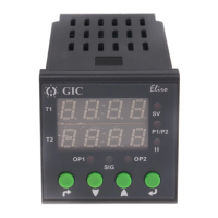
Shows current time, setting values, or operation status. Can be programmed to show different default modes.

Mode Selection

Selects the timing operation mode. Press to cycle through modes.

Parameter;Value Adjustment

Adjusts timing parameters, set values, or selects options. Press to increment, hold to auto-increment.

Up;Down Counting;Down Setting

Used for setting timing values or selecting modes. Press to change value by one step.

Reset;Start

Resets the timer or starts the timing operation. Press and hold for 3 seconds to reset to factory default.

Power;Signal Input

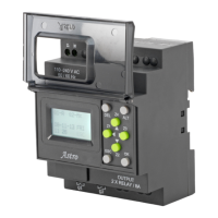
Connection terminals for power supply and signal inputs.

Connector Diagram

Sensor Input

Input for PNP sensor, NTC sensor, or switch type inputs.

Power Supply Terminals

Terminals for AC 100-240V or DC 12-240V power connection.

Output Relay Terminals

Terminals for connecting the output relay contacts (NO, NC, Common).

Product Specifications

Supply Characteristics

Details voltage range (100-240V AC, 50/60 Hz) and power consumption.

Output Signal

Specifies the relay output type (SPDT) and contact rating.

Feature Explanation

Describes key features like programmable modes, high accuracy, and digital display.

Environmental

Covers operating/storage temperature, humidity, and protection ratings (IP54).

EMC;CE Compliance

Lists compliance with EMC directives and relevant standards.

Operating Mode & Description

MODE 01: DELAY ON TIME (DT)

Output is ON after delay period. Output turns OFF when input signal is removed.

MODE 02: DELAY OFF TIME (RT)

Output is OFF after delay period. Output turns ON when input signal is removed.

MODE 03: INTERVAL ON (INT)

Output is ON during delay period. Output turns OFF when delay is complete.

MODE 04: INTERVAL OFF (RI)

Output is OFF during delay period. Output turns ON when delay is complete.

MODE 05: CYCLIC ON (CC)

Output cycles ON/OFF repeatedly after input signal is applied.

MODE 06: SIGNAL ON (SO)

Output is ON as long as input signal is present.

MODE 07: SIGNAL OFF (SF)

Output is OFF as long as input signal is present.

MODE 08: DELAY ON TIME (DUAL MODE)

Output ON after first delay, then OFF after second delay. Two independent delays.

MODE 09: INTERVAL ON (DUAL MODE)

Output ON for first delay, then OFF for second delay. Two independent delays.

MODE 10: DELAY ON TIME (PULSE)

Output is ON after delay. Output turns OFF after a short pulse duration.

MODE 11: DELAY OFF TIME (PULSE)

Output is OFF after delay. Output turns ON for a short pulse duration.

MODE 12: INTERVAL ON (PULSE)

Output is ON for a delay period. Output turns OFF after a short pulse duration.

MODE 13: INTERVAL OFF (PULSE)

Output is OFF for a delay period. Output turns ON for a short pulse duration.

MODE 14: DELAY ON TIME (START;STOP)

Delay starts on input signal, stops on second input signal. Output ON after delay.

MODE 15: DELAY OFF TIME (START;STOP)

Delay starts on input signal, stops on second input signal. Output OFF after delay.

MODE 16: INTERVAL ON (START;STOP)

Interval starts on input signal, stops on second input signal. Output ON during interval.

MODE 17: INTERVAL OFF (START;STOP)

Interval starts on input signal, stops on second input signal. Output OFF during interval.

MODE 18: ACCUMULATION DELAY ON TIME

Delay time accumulates with intermittent ON signals. Output ON after total delay.

MODE 19: ACCUMULATION DELAY OFF TIME

Delay time accumulates with intermittent OFF signals. Output OFF after total delay.

MODE 20: UP;DOWN COUNTER

Counts pulses. Output changes state when count reaches set value.

MODE 21: MANUAL OPERATION

Allows manual ON/OFF control of the output via front panel buttons.

MODE 22: AUTO OPERATION

Output operates automatically based on selected timing mode and settings.

MODE 23: DELAY ON TIME (S;S)

Output ON after delay. Start/Stop input signal controls delay progression.

MODE 24: DELAY OFF TIME (S;S)

Output OFF after delay. Start/Stop input signal controls delay progression.

MODE 25: INTERVAL ON (S;S)

Output ON during interval. Start/Stop input signal controls interval progression.

MODE 26: INTERVAL OFF (S;S)

Output OFF during interval. Start/Stop input signal controls interval progression.

MODE 27: DELAY ON TIME (MONO)

Output ON after delay. Output stays ON for a fixed pulse duration.

MODE 28: DELAY OFF TIME (MONO)

Output OFF after delay. Output stays OFF for a fixed pulse duration.

MODE 29: INTERVAL ON (MONO)

Output ON for interval. Output stays ON for a fixed pulse duration.

MODE 30: INTERVAL OFF (MONO)

Output OFF for interval. Output stays OFF for a fixed pulse duration.

MODE 31: DELAY ON TIME (DUAL TIME)

Output ON after first delay, then OFF after second delay. Two independent delays.

MODE 32: DELAY OFF TIME (DUAL TIME)

Output OFF after first delay, then ON after second delay. Two independent delays.

MODE 33: INTERVAL ON (DUAL TIME)

Output ON for first interval, then OFF for second interval. Two independent intervals.

MODE 34: INTERVAL OFF (DUAL TIME)

Output OFF for first interval, then ON for second interval. Two independent intervals.

MODE 35: DELAY ON TIME (DUAL TIME)

Output ON after first delay, then ON again after second delay. Two independent delays.

GIC Eliro V7DDSS3Eliro V7DFTS3 Specifications

General IconGeneral
BrandGIC
ModelEliro V7DDSS3Eliro V7DFTS3
CategoryTimer
LanguageEnglish

Related product manuals