EasyManua.ls Logo

GIESSE RACK MAX 650 User Manual

GIESSE RACK MAX 650
136 pages
Go to English
To Next Page IconTo Next Page
Page #1 background imageLoading...
Page #1 background image
I1055000/05-2021
RACK MAX 650
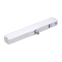
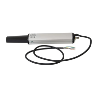
ATTUATORE A CREMAGLIERA
FORZA 650 N - CORSE 180, 230, 350, 550, 750, 1000 MM
ALIMENTAZIONE ELETTRICA 110-230V~(A.C.) 50/60HZ E 24V (D.C.)
RACK ACTUATOR
FORCE 650 N - STROKES 180, 230, 350, 550, 750, 1000 MM
ELECTRICAL POWER SUPPLY 110-230V~(A.C.) 50/60HZ AND 24V (D.C.)
ACTUADOR DE CREMALLERA
FUERZA 650 N - CARRERAS 180, 230, 350, 550, 750, 1000 MM
ALIMENTACIÓN ELÉCTRICA 110-230V~ (A.C.) 50/60HZ Y 24V (D.C.)
OPÉRATEUR À CRÉMAILLÈRE
FORCE 650 N - COURSES 180, 230, 350, 550, 750, 1000 MM
ALIMENTATION ELECTRIQUE 110-230V~ (A.C.) 50/60HZ ET 24V (D.C.)
РЕЕЧНЫЙ ПРИВОД
УСИЛИЕ 650 Н ХОД 180, 230, 350, 550, 750, 1000 ММ
ЭЛЕКТРОПИТАНИЕ 110-230V~ (A.C.) 50/60HZ E 24V (D.C.)
Italiano MANUALE D’USO E INSTALLAZIONE
English INSTRUCTION AND INSTALLATION MANUAL
Español MANUAL DE USO E INSTALACIÓN
Français MANUEL D'UTILISATION ET D'INSTALLATION
Русский РУКОВОДСТВО ПО ЭКСПЛУАТАЦИИ

Table of Contents

Questions and Answers:

GIESSE RACK MAX 650 Specifications

General IconGeneral
BrandGIESSE
ModelRACK MAX 650
CategoryController
LanguageEnglish

Summary

Symbols used in the manual

1. Security rules

2. Formulas and recommendations for installation

2.1. Calculation of opening / closure force

Formulae to calculate the force required to open or close a window.

2.2. Maximum opening in accordance with sash height

Guidance on selecting actuator stroke based on window sash height.

3. Technical information about function

4. Construction and standards

5. Use of synchronized Rack Max 650 24 V dc actuator

6. Actuator dimensions

7. Id plate and marking data

8. Technical data

9. Electric power supply

9.1. Power supply cable cross-sections

Table showing maximum cable lengths for different cable cross-sections and voltages.

10. Actuator assembly instructions

10.1. Preparing for assembly

Preparation steps and required materials before actuator assembly.

10.2. Calculating the number of thrust / fastening points

Formula and method to determine optimal thrust/fastening point locations.

10.3. Installation on top-hung opening window

Step-by-step guide for installing the actuator on top-hung windows.

10.4. Installation on domes, skylights or Shed windows

Instructions for installing actuators on dome or skylight windows.

10.5. Installation of actuator and rod (or drive) with connection bar

Procedure for connecting actuators using a mechanical connection bar.

10.6. Installation of multiple actuators with a connection bar or in synchronized mode

Guide for installing multiple actuators mechanically or synchronously.

11. Electrical connection

11.1. RACK MAX 650 electrical connection

Wiring diagrams and instructions for single RACK MAX 650 units.

11.2. Connection of 2 or more synchronized RACK MAX 650 24 V ac

Wiring instructions for connecting multiple synchronized actuators.

12. Programming the actuator

12.1. Reset procedure

Procedure to configure actuator parameters and perform initial setup.

12.2. Actuator limit stop

Explanation of automatic limit stop positioning for opening and closing.

12.3. Step acquisition

Procedure to acquire the correct window step after reset.

12.4. LED signals

Explanation of LED indicators for status and errors.

13. Inspecting assembly for errors

14. Emergency operation and opening for maintenance or cleaning

15. Troubleshooting

16. Environmental protection

17. Certificate of guarantee

18. EU Declaration of Conformity

19. EU Declaration of Conformity

20. Declaration of Incorporation

21. Declaration of Incorporation

Related product manuals