- 24 -
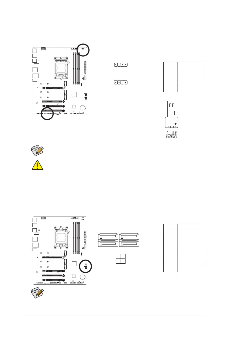
Pin No. Denition
1 GND
2 TXP
3 TXN
4 GND
5 RXN
6 RXP
7 GND
To enable hot-plugging for the SATA ports, please navigate to the "BIOS Setup" page of
GIGABYTE's website and search for "SATA Conguration" for more information.
9) SATA3 0/1/2/3 (SATA 6Gb/s Connectors)
The SATA connectors conform to SATA 6Gb/s standard and are compatible with SATA 3Gb/s and SATA
1.5Gb/s standard. Each SATA connector supports a single SATA device. The SATA connectors support
RAID 0, RAID 1, and RAID 10. Please navigate to the "Conguring a RAID Set" page of GIGABYTE's
website for instructions on conguring a RAID array.
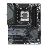
8)
ARGB_V2_1jk/ARGB_V2_2jk/ARGB_V2_3 (Addressable RGB Gen2 LED Strip Headers)
The headers can be used to connect a standard 5050 addressable RGB Gen2 LED strip, with maximum
power rating of 3A (5V) and maximum number of 256 LEDs.
For how to turn on/off the lights of the LED strip, please navigate to the "Unique Features" page
of GIGABYTE's website.
Pin No. Denition
1 V (5V)
2 Data
3 No Pin
4 GND
Connect your addressable RGB Gen2 LED strip to the header. The power pin
(marked with a triangle on the plug) of the LED strip must be connected to
Pin 1 of the addressable RGB Gen2 LED strip header. Incorrect connection
may lead to the damage of the LED strip.
Addressable RGB Gen2
LED Strip
1
• To avoid abnormal LED behavior, do not connect addressable RGB Gen1 LED strips and
addressable RGB Gen2 LED strips to the same header at the same time.
• Before installing or removing the devices, be sure to turn off the devices and your computer.
Unplug the power cord from the power outlet to prevent damage to the devices.
1
ARGB_V2_1jk/ARGB_V2_3
1
ARGB_V2_2jk
SATA3
2 0
3 1
1
1
7
7
j Only for B650 EAGLE AX.
k Only for B650 EAGLE.