- 9 -
USB CPU:
- 1 x USB Type-C
®
port on the back panel, with USB 3.2 Gen 2 support
- 2 x USB 3.2 Gen 2 Type-A ports (red) on the back panel
CPU + USB 2.0 Hub:
- 4 x USB 2.0/1.1 ports available through the F_USB header on the front of
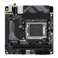
GC-B650I BTB PLUG
Chipset:
- 1 x USB Type-C
®
port with USB 3.2 Gen 2x2 support, available through the
internal USB header
- 4 x USB 3.2 Gen 1 ports (2 ports on the back panel, 2 ports available through
the internal USB header)
- 2 x USB 2.0/1.1 ports on the back panel
Internal
Connectors
1 x 24-pin ATX main power connector
1 x 8-pin ATX 12V power connector
1 x CPU fan header
1 x CPU fan/water cooling pump header
1 x system fan header (SYS_FAN1
(Note 1)
)
1 x addressable LED strip header
(Note 2)
1 x RGB LED strip header
(Note 1)
3 x M.2 Socket 3 connectors (M2B_CPU
(Note 2)
/M2A_CPU
(Note 3)
/M2C_SB
(Note 4)
)
4 x SATA 6Gb/s connectors
(Note 1)
1 x front panel header
(Note 1)
1 x front panel audio header (routed from the adapter card on the rear panel)
1 x USB Type-C
®
header, with USB 3.2 Gen 2x2 support
1 x USB 3.2 Gen 1 header
1 x USB 2.0/1.1 header
(Note 2)
1 x reset button
(Note 2)
1 x reset jumper
1 x power switch jumper
1 x Clear CMOS jumper
Back Panel
Connectors
1 x DisplayPort
1 x HDMI port
1 x USB Type-C
®
port (DisplayPort), with USB 3.2 Gen 2 support
2 x USB 3.2 Gen 2 Type-A ports (red)
2 x USB 3.2 Gen 1 ports
2 x USB 2.0/1.1 ports
1 x RJ-45 port
2 x SMA antenna connectors (2T2R)
1 x Q-Flash Plus button
2 x audio jacks
(Note 1) The connector is on the front of GC-B650I FRONT CARD.
(Note 2) The connector is on the front of GC-B650I BTB PLUG.
(Note 3) The connector is on the back of GC-B650I BTB PLUG.
(Note 4) The connector is on the back of the motherboard.
 Loading...