EasyManuals Logo

Gigabyte B660I AORUS PRO DDR4 User Manual

Gigabyte B660I AORUS PRO DDR4
36 pages
To Next Page IconTo Next Page
To Previous Page IconTo Previous Page
Page #23 background imageLoading...
Page #23 background image
- 23 -
The front panel design may differ by chassis. A front panel module mainly consists of power
switch, reset switch, power LED, hard drive activity LED and etc. When connecting your chassis
front panel module to this header, make sure the wire assignments and the pin assignments are
matched correctly.
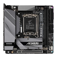
10) F_PANEL (Front Panel Header)
Connect the power switch, reset switch, and system status indicator on the chassis to this header according
to the pin assignments below. Note the positive and negative pins before connecting the cables.
PW (Power Switch):
Connects to the power switch on the chassis front panel. You may congure the way to turn off your
system using the power switch (please navigate to the "BIOS Setup" page of GIGABYTE's website and
search for "Soft-Off by PWR-BTTN" for more information).
HD (Hard Drive Activity LED):
Connects to the hard drive activity LED on the chassis front panel. The LED is on when the hard drive
is reading or writing data.
RES (Reset Switch):
Connects to the reset switch on the chassis front panel. Press the reset switch to restart the computer
if the computer freezes and fails to perform a normal restart.
NC: No connection.
PLED/PWR_LED (Power LED):
Connects to the power status indicator on the chassis front panel. The LED
is on when the system is operating. The LED is off when the system is in S3/
S4 sleep state or powered off (S5).
System Status LED
S0 On
S3/S4/S5 Off
1
2
9 10
NC
PLED-
PW-
PLED+
PW+
HD-
RES+
HD+
RES-
Power Switch
Hard Drive
Activity LED
Reset Switch
Power LED
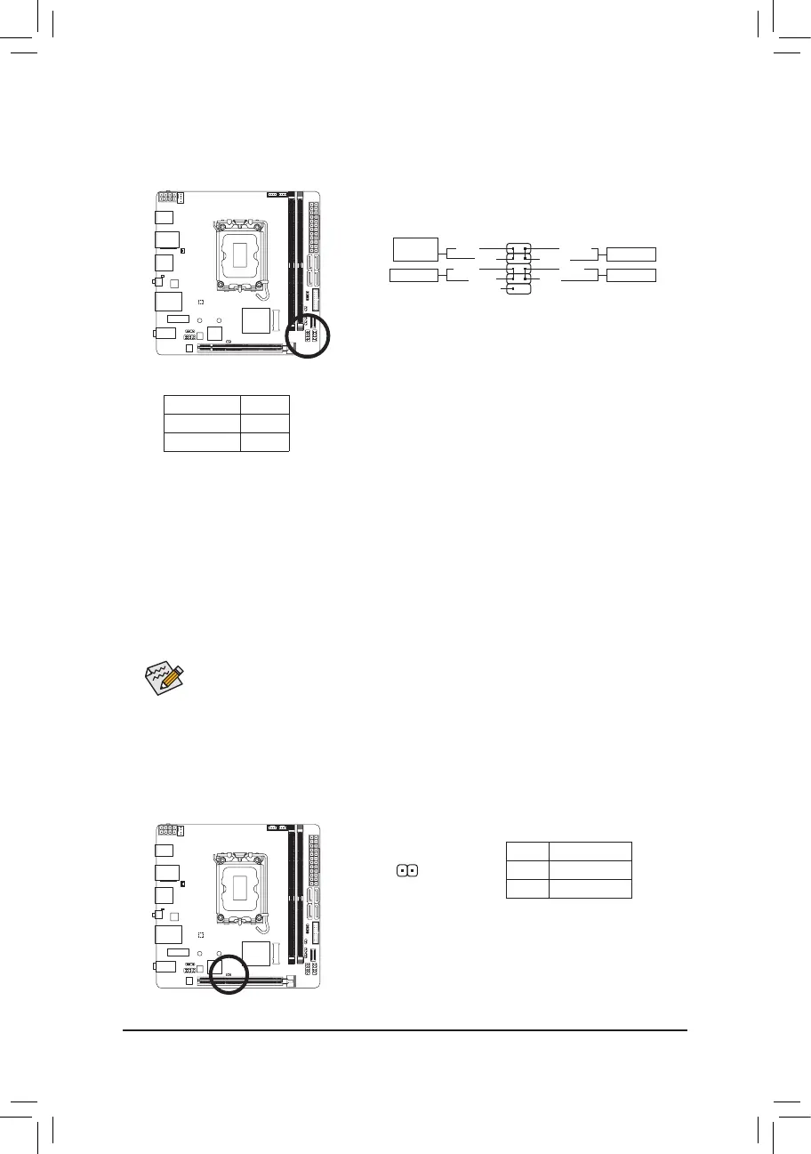
11) CI (Chassis Intrusion Header)
This motherboard provides a chassis detection feature that detects if the chassis cover has been removed.
This function requires a chassis with chassis intrusion detection design.
Pin No. Denition
1 Signal
2 GND
1

Questions and Answers:

Question and Answer IconNeed help?

Do you have a question about the Gigabyte B660I AORUS PRO DDR4 and is the answer not in the manual?

Gigabyte B660I AORUS PRO DDR4 Specifications

General IconGeneral
Processor socketLGA 1700
Processor manufacturerIntel
Compatible processor seriesIntel Celeron, Intel Core i3, Intel Core i5, Intel Core i7, Intel Core i9, Intel Pentium
Maximum number of SMP processors1
Component forPC
Motherboard chipsetIntel B660
PC health monitoringCPU, FAN, Temperature, Voltage
Audio output channels7.1 channels
Motherboard form factormini ITX
Windows operating systems supportedWindows 10 x64, Windows 11 x64
S/PDIF out portYes
DisplayPort version1.2
USB 2.0 ports quantity2
USB 3.2 Gen 1 (3.1 Gen 1) Type-A ports quantity4
USB 3.2 Gen 2 (3.1 Gen 2) Type-A ports quantity0
Wi-Fi standards802.11a, 802.11b, 802.11g, Wi-Fi 4 (802.11n), Wi-Fi 5 (802.11ac), Wi-Fi 6 (802.11ax)
Bluetooth version5.2
Top Wi-Fi standardWi-Fi 6 (802.11ax)
Ethernet interface type2.5 Gigabit Ethernet
Memory slots typeDIMM
Supported memory typesDDR4-SDRAM
Maximum internal memory64 GB
Supported memory clock speeds2133, 2400, 2666, 2933, 3000, 3200, 3300, 3333, 3400, 3466, 3600, 3666, 3733, 3800, 3866, 4000, 4133, 4266, 4300, 4400, 4500, 4600, 4700, 4800, 4933, 5000, 5133, 5333 MHz
Cables includedSATA
BIOS typeUEFI AMI
ACPI version5.0
BIOS memory size256 Mbit
System Management BIOS (SMBIOS) version2.7
Maximum resolution4096 x 2160 pixels
Parallel processing technology supportNot supported
RAID levels0, 1, 5, 10
Supported storage drive typesHDD & SSD
Supported storage drive interfacesM.2, SATA III
Harmonized System (HS) code84733020
Weight1000 g
Weight and Dimensions IconWeight and Dimensions
Width170 mm
Height70 mm

Related product manuals