Do you have a question about the Gigabyte G190-H44 and is the answer not in the manual?
This document outlines the assembly procedures for the GIGABYTE G190-H44 server, providing a detailed work instruction for system integration engineering. The primary function of this document is to standardize the assembly process at the DVT (Design Verification Test) stage, ensuring that the methodologies are effectively transferred to the manufacturing factory. This standardization is crucial for maintaining consistent quality and efficiency in server production.
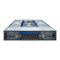
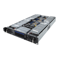
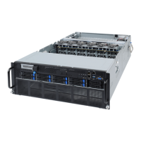
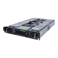
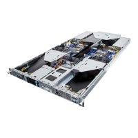
The G190-H44 is a server system designed for robust performance, and its assembly involves several key steps that are meticulously detailed to prevent errors and ensure proper functionality. The assembly process begins with the removal of the top cover, which is secured by 14 screws. This initial step grants access to the internal components, preparing the server for subsequent modifications or installations. The document emphasizes the importance of carefully removing these screws to avoid damage to the chassis or the internal structure.
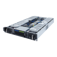
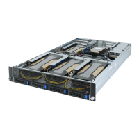
A critical aspect of the assembly involves managing the server's cooling system, specifically the fan ducts. The central fan duct needs to be removed to facilitate access to other components. This step is detailed with an instruction to unscrew and then remove the fan duct, followed by re-securing the screws. This temporary removal is essential for working on underlying components without obstruction. The document provides visual aids, such as circled areas in images, to clearly indicate the screws that need to be manipulated, enhancing clarity and reducing the likelihood of missteps during assembly.
Cable management is another significant feature addressed in the assembly instructions. The document specifies the removal of cable ties on both sides of the server. Proper cable management is vital for airflow, preventing overheating, and ensuring easy access for future maintenance or upgrades. By removing these ties, technicians can reposition cables as needed during the assembly process, ensuring they do not interfere with component installation or airflow. The instructions are accompanied by images that highlight the exact locations of these cable ties, making it straightforward for the assembler to identify and remove them.
The server's cooling system is further detailed with instructions for handling the right and left fan ducts. These components are crucial for directing airflow efficiently across the server's internal hardware, preventing thermal throttling and ensuring stable operation. The document illustrates the distinct shapes and orientations of the right and left fan ducts, which is important for correct reinstallation. Understanding the specific placement of each duct is key to optimizing the server's thermal performance.
The reinstallation of the fan ducts is a multi-step process. First, the left fan duct is placed into its designated position. This step is followed by the placement of the right fan duct. Finally, the central fan duct, which was initially removed, is reinstalled. This sequential reinstallation ensures that all cooling components are correctly seated and aligned, providing optimal airflow management within the server chassis. The document provides clear images for each of these steps, showing the fan ducts being placed into their respective positions, which helps in verifying correct installation.
The GIGABYTE G190-H44 assembly manual is designed to be a comprehensive guide for technicians. Its usage features include clear, step-by-step instructions accompanied by high-quality images. Each step is numbered and described in detail, with specific actions like "remove screws" or "place fan duct" clearly articulated. The inclusion of "Part number / Board model name" and "Q'ty" columns in the instruction table suggests that the document is also used for inventory and quality control purposes, ensuring that the correct components are used in the right quantities during assembly. The "Comment" section allows for additional notes or specific instructions pertinent to each step, further enhancing the clarity of the process.
Maintenance features are implicitly supported by the detailed assembly instructions. By understanding how the server is put together, technicians can more easily disassemble it for repairs, component upgrades, or routine cleaning. For instance, the instructions for removing fan ducts and the top cover are directly applicable to maintenance tasks that require access to internal components. The emphasis on proper screw management and cable routing during assembly also contributes to easier maintenance, as components are less likely to be obstructed or damaged during future servicing.
The document's structure, with sections for "Overview," "Document History," and "Purpose," provides a robust framework for managing the assembly process. The "Document History" section, which logs revisions and originators, ensures traceability and accountability for changes made to the assembly procedure. This is particularly important in a manufacturing environment where process changes need to be carefully managed and documented. For example, the entry "Install 145W Fan fuct" with a date and originator indicates a specific update to the assembly process, likely related to a component change or an improvement in cooling efficiency.
The "Purpose" section explicitly states that the document aims to define Gigabyte's requirements for standard server assembly at the DVT stage and to transfer this method to the factory. This highlights the document's role as a bridge between design verification and mass production, ensuring that the lessons learned during the DVT phase are incorporated into the factory assembly line. This systematic approach helps in scaling production while maintaining the quality and performance standards established during the design phase.
Overall, the GIGABYTE G190-H44 assembly notice and work instruction serve as a critical tool for ensuring the precise and efficient construction of the server system. Its detailed, visually supported, and systematically organized content makes it an invaluable resource for both initial assembly and subsequent maintenance activities, contributing to the overall reliability and longevity of the GIGABYTE G190-H44 server. The emphasis on clear communication and visual guidance minimizes errors and streamlines the production process, which is essential for complex electronic assemblies like server systems.
| Model | G190-H44 |
|---|---|
| Memory Type | DDR4 |
| Storage Support | SATA/SAS |
| Operating System Support | Windows Server, Linux |
| Memory Slots | 16 x DIMM slots |
| Maximum Memory | 2 TB |
| Storage Bays | 8 x 2.5" hot-swap drive bays (SAS/SATA) |
| SAS Controller | Optional |
| Power Supply | 800W Redundant (1+1) |
| Form Factor | 1U Rackmount |