- 22 -
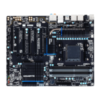
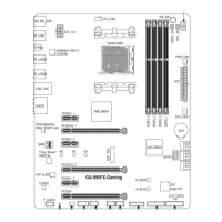
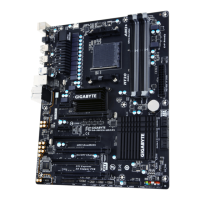
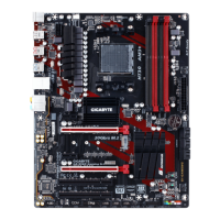
In addition to the default speakers settings, the ~ audiojackscanbereconguredtoperform
different functions via the audio software. Only microphones still MUST be connected to the
defaultMicinjack( ).Refertotheinstructionsonsettingupa2/4/5.1/7.1-channelaudiocon-
gurationinChapter5,"Conguring2/4/5.1/7.1-ChannelAudio."
Center/Subwoofer Speaker Out Jack (Orange)
Usethisaudiojacktoconnectcenter/subwooferspeakersina5.1/7.1-channelaudioconguration.
Rear Speaker Out Jack (Black)
Thisjackcanbeusedtoconnectfrontspeakersina7.1-channelaudioconguration.
Side Speaker Out Jack (Gray)
Usethisaudiojacktoconnectsidespeakersina4/5.1/7.1-channelaudioconguration.
Line In Jack (Blue)
The default line out jack. Use this audio jack for line in devices such as an optical drive, walkman, etc.
Line Out Jack (Green)
The default line out jack. Use this audio jack for a headphone or 2-channel speaker. This jack can be used
toconnectfrontspeakersina4/5.1/7.1-channelaudioconguration.
Mic In Jack (Pink)
The default Mic in jack. Microphones must be connected to this jack.
• Whenremovingthecableconnectedtoabackpanelconnector,rstremovethecablefromyour
device and then remove it from the motherboard.
• When removing the cable, pull it straight out from the connector. Do not rock it side to side to prevent
an electrical short inside the cable connector.

 Loading...