Do you have a question about the Gigabyte GA-G41MT-S2 and is the answer not in the manual?
Guidelines and warnings for safe and proper installation to prevent damage.
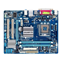
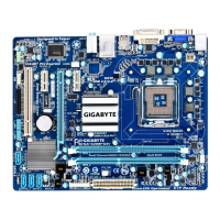
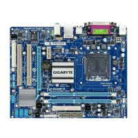
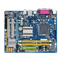
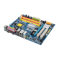
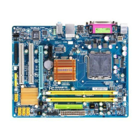
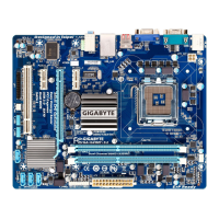
Details the technical features, components, and capabilities of the motherboard.
Step-by-step instructions for correctly installing the processor onto the motherboard socket.
Guide on how to properly insert DDR3 DIMM modules into the motherboard slots.
Procedures and precautions for installing PCI or PCI Express expansion cards.
Identifies and describes the ports and connectors located on the motherboard's rear panel.
Details the internal headers and connectors on the motherboard for system components.
Displays the initial boot screen showing BIOS version and model information.
Overview of the BIOS setup utility's primary screen and navigation methods.
Section for adjusting CPU, memory, and chipset frequencies and timings for performance.
Configuration settings for system date, time, and IDE/SATA devices.
Options for controlling boot order, security, and advanced system functionalities.
Settings related to the motherboard's chipset, including graphics and memory modes.
Configuration for onboard devices like audio, LAN, serial, and parallel ports.
Options to control system power states, wake-up events, and energy saving.
Settings for Plug and Play (PnP) and Peripheral Component Interconnect (PCI) bus configurations.
Monitors system voltages, temperatures, and fan speeds, and manages chassis intrusion detection.
Resets BIOS settings to the safest and most stable configuration for troubleshooting.
Resets BIOS settings to the manufacturer's recommended optimal configuration.
Allows setting passwords for BIOS access and system startup security.
Saves current BIOS settings and exits the setup utility.
Discards any changes made in BIOS setup and exits the utility.
| Memory voltage | 1.5 V |
|---|---|
| Number of memory slots | 2 |
| Supported memory types | DDR3-SDRAM |
| Maximum internal memory | 8 GB |
| Supported memory clock speeds | 800, 1066, 1333 MHz |
| Processor socket | LGA 775 (Socket T) |
| Processor manufacturer | Intel |
| Compatible processor series | Intel Celeron, Intel Pentium |
| CPU fan connector | Yes |
| Number of SATA connectors | 4 |
| Number of Parallel ATA connectors | 1 |
| eSATA ports quantity | - |
| USB 2.0 ports quantity | USB 2.0 ports have a data transmission speed of 480 Mbps, and are backwards compatible with USB 1.1 ports. You can connect all kinds of peripheral devices to them. |
| Firewire (IEEE 1394) ports | 0 |
| Component for | PC |
| Power source type | ATX |
| Motherboard chipset | Intel® G41 |
| Audio output channels | 7.1 channels |
| Motherboard form factor | micro ATX |
| Motherboard southbridge | Intel ICH7 |
| Compatible operating systems | Microsoft Windows 7/Vista/XP |
| Supported storage drive interfaces | SATA |
| Parallel processing technology support | Not supported |
| LAN controller | Atheros AR8151 |
| Networking features | Gigabit Ethernet |
| BIOS type | AWARD |
| ACPI version | 1.0b |
| Depth | 194 mm |
|---|---|
| Width | 244 mm |