Do you have a question about the Gigabyte GA-G41MT-D3 and is the answer not in the manual?
Read and follow safety procedures before installing motherboard to prevent damage.
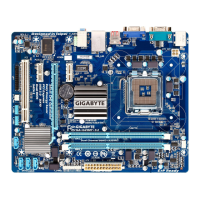
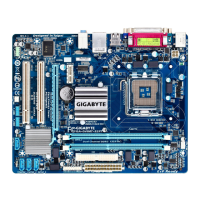
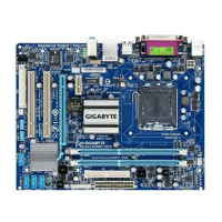
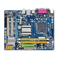
Details CPU, Chipset, Memory, Graphics, Audio, LAN, Expansion Slots, Storage, USB, and Internal Connectors.
Guide to installing the CPU and its associated cooling system safely.
Instructions for correctly installing RAM modules into the motherboard slots.
Steps for adding expansion cards like graphics or sound cards to the motherboard.
Description and function of all external ports located on the motherboard's rear panel.
Details on various internal headers and connectors on the motherboard for system components.
Explanation of ATX 12V and 2x12 Main Power Connector pinouts and function.
Information on CPU_FAN and SYS_FAN headers for connecting system fans.
Guide to connecting IDE and SATA storage devices to the motherboard.
Instructions for connecting chassis front panel components like power and reset switches.
Details on connecting front panel audio module for HD and AC'97 audio.
Information on S/PDIF and USB header connections for audio and peripherals.
Details on COM header for serial ports and CLR_CMOS jumper for resetting BIOS.
Instructions for replacing the CMOS battery and clearing CMOS values.
Displays the initial screens shown when the computer boots up.
Overview of the BIOS Setup main menu and navigation using arrow keys and Enter.
Advanced settings for tweaking CPU, memory, and system performance.
Explanation of F11 and F12 keys for saving and loading BIOS settings.
Configuration of system voltages including CPU Vcore, Termination, Reference, and DRAM.
Detailed settings for memory timing parameters like CAS Latency and tRCD.
Configuration of basic system settings like date, time, and IDE/SATA devices.
Settings for boot priority, CPU features, memory protection, and virtualization.
Configuration options for onboard VGA, PAVP mode, and display initialization.
Enabling/disabling onboard IDE, SATA, Audio, LAN, and USB controllers.
Settings for ACPI sleep states, wake-up events, and power-on options.
Configuration of Plug and Play (PnP) and PCI slot IRQ assignments.
Displays system voltages, temperatures, fan speeds, and warnings.
Restores the system to the safest and most stable BIOS default settings.
Applies the optimal BIOS default settings for system operation.
Configure system passwords for BIOS access and startup.
Saves current BIOS settings to CMOS and exits the setup utility.
Exits BIOS Setup without saving any changes made.
Procedure for installing essential chipset drivers from the motherboard driver disk.
Information on Restriction of Hazardous Substances and Waste Electrical directives.
Explanation of the WEEE symbol and recycling procedures for electronic waste.
Table detailing hazardous substance content in product components per China RoHS.
Details on accessing GIGABYTE's online technical support system.
| Memory voltage | 1.5 V |
|---|---|
| Number of memory slots | 2 |
| Maximum internal memory | 4 GB |
| Supported memory clock speeds | 1066 MHz |
| Processor socket | LGA 775 (Socket T) |
| Processor manufacturer | Intel |
| Processor system buses supported | 1333 MHz |
| S/PDIF out connector | Yes |
| Number of SATA connectors | 4 |
| Number of EATX power connectors | 1 |
| Controller 2nd interface type | iTE IT8718 |
| Headphone outputs | 3 |
| USB 2.0 ports quantity | USB 2.0 ports have a data transmission speed of 480 Mbps, and are backwards compatible with USB 1.1 ports. You can connect all kinds of peripheral devices to them. |
| Firewire (IEEE 1394) ports | 0 |
| Audio chip | Realtek ALC888B |
| Power source type | ATX |
| Audio output channels | 7.1 channels |
| Motherboard form factor | micro ATX |
| Compatible operating systems | Windows 7/Vista/XP |
| Graphics card | GMA X4500 |
| Parallel processing technology support | Not supported |
| Networking features | Gigabit Ethernet |
| BIOS type | AWARD |
| ACPI version | 1.0 |
| BIOS memory size | 16 Mbit |
| Depth | 194 mm |
|---|---|
| Width | 244 mm |