Do you have a question about the Gigabyte R282-Z90 and is the answer not in the manual?
Detailed info on installation, configuration, and use of product covering hardware & BIOS.
Detailed info on add-on hardware or software component installation & use.
Short guide with visual diagrams for installation purposes.
Guidelines for handling electronic components to prevent damage from static electricity.
Procedure for safely removing power from the system before servicing.
Precautions for dealing with hazardous electrical conditions on cables.
Specific instructions on how to handle sensitive circuit boards.
Detailed steps and precautions for handling motherboard jumpers.
Safety guidelines and procedures to prevent damage during installation.
Detailed specifications for CPU, Chipset, Memory, LAN, Video, and Expansion Slots.
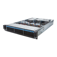
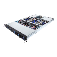
Visual representation of system components and their interconnections.
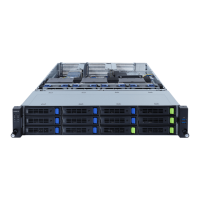
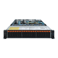
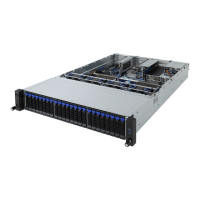
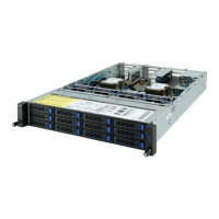
Description and identification of front-panel components like HDD bays and USB ports.
Identification of rear-panel ports and connectors including PCIe slots and PSUs.
Explanation of front panel buttons and LED indicators for system status.
Details on the function and status indicated by rear system LAN LEDs.
Information on the status indicated by the power supply unit's LED.
Explanation of LED indicators for hard disk drives, including fault and activity status.
Essential safety guidelines before starting any hardware installation procedure.
Step-by-step guide for safely removing and reinstalling the server chassis cover.
Procedure for removing and reinstalling the internal fan duct for cooling.
Instructions for safely removing and installing the CPU heat sink for thermal management.
Detailed steps for safely removing and installing CPU modules, including orientation.
Covers installation, removal, and population tables for DDR4 memory modules.
Steps for installing or removing PCIe cards, including use of riser brackets.
Procedures for installing OCP 3.0 and OCP 2.0 mezzanine cards.
Instructions for installing 3.5" HDDs (R282-Z90) and 2.5" HDDs (R282-Z91/Z92).
Steps for installing or removing an M.2 device, including thermal pad and screw placement.
Guide for replacing the system fan assembly using release latches.
Procedure for replacing a redundant power supply unit, including retaining clips.
Diagrams illustrating cable routing for R282-Z90, R282-Z91, and R282-Z92 models.
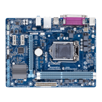
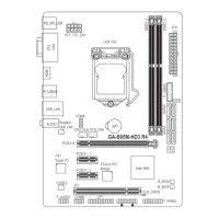
Labeled diagram identifying key connectors and components on the motherboard.
Explanation of jumper settings for Clear CMOS, SMBUS, PMBUS, BIOS password, and NCSI.
Table detailing function keys for navigating and operating the BIOS setup utility.
Overview of the BIOS Main Menu screen, navigation, and help features.
Section detailing configuration options for various hardware components.
Settings related to Trusted Platform Module (TPM) support and security features.
Displays PSP firmware version information, which is non-configurable.
Option to select between onboard or external VGA support.
Configuration settings for the AST2500 Super IO chip.
Controls system wake-up behavior from S5 state based on time.
Configuration for enabling and setting up serial port console redirection for remote management.
Settings related to CPU virtualization (SVM) and Secure Memory Encryption (SMEE).
Configuration options for PCIe lanes, I/O ROM, and Above 4G Decoding.
Settings for Legacy USB support, XHCI hand-off, and USB hardware timeouts.
Displays information about connected NVMe controllers and drives.
Displays detected SATA devices and their configurations.
Settings for enabling/disabling UEFI network stack features like PXE and HTTP boot.
Displays status information for CPU memory channels, DRAM, and parity.
Configuration settings for the iSCSI initiator name and connection attempts.
Settings for configuring server and client certificates for TLS authentication.
Configuration details for the Intel I350 Gigabit Network Controller.
Settings for creating, configuring, and managing VLANs for network segmentation.
Configuration for static or DHCP-based IPv4 network settings.
Configuration for IPv6 network settings, including interface ID and DNS.
Menu for configuring CPU-related information and settings managed by the BIOS.
BIOS settings related to CPU performance, prefetchers, and watchdog timers.
Configuration options for memory scrubbing and ACPI settings related to DRAM.
Settings for DDR4 memory controller, CAD bus, data bus, and RAS configurations.
Configuration for IOMMU, PCIe ARI, and HD Audio features.
Settings for SMU, NBIO RAS, and PCIe link training.
Configuration options for FCH SATA, USB, and SD dump settings.
Control settings for ABL console output and miscellaneous SOC functions.
Menu for configuring AMD PBS (Platform BIOS settings) and SPI locking.
Settings for Reliability, Availability, and Serviceability (RAS) features, including SMI control.
Configuration options for PCIe link training and compliance mode.
Settings for server management features like FRB-2 Timer and OS Watchdog.
Configuration for enabling, disabling, and managing the System Event Log (SEL).
Displays basic system identification and product information (non-configurable).
Settings for configuring BMC network parameters, including IP address and MAC.
Configuration for enabling/disabling IPv6 BMC LAN channels and IP address source.
Options for setting administrator and user passwords to protect system access.
Settings for enabling/disabling Secure Boot and managing boot keys and modes.
Configuration for system boot order, boot modes, and setup timeout.
Specifies boot device priority from available UEFI network drives.
Specifies boot device priority from available UEFI applications.
Options for saving changes, discarding them, restoring defaults, or launching EFI Shell.
Lists POST codes for processor, memory, and PMU test points.
Lists various POST codes related to AGESA modules.
Universal POST codes for ACPI and SMBIOS related events.
Memory-specific POST codes relevant to CZ systems.
POST codes related to S3 interface operations.
POST codes related to PMU operations.
POST codes assigned for AGESA PSP module operations.
POST codes for AGESA NBIO module operations.
POST codes for AGESA CCX module operations.
POST codes for AGESA DF module operations.
POST codes for AGESA FCH module operations.
Information on BIOS POST beep codes and their meanings.
Beep codes indicating status during the PEI phase of POST.
Beep codes indicating status during the DXE phase of POST.
Instructions for recovering the BIOS if it becomes corrupt using embedded techniques.
| Processor family | AMD |
|---|---|
| Processor socket | Socket SP3 |
| Built-in processor | No |
| Motherboard chipset | - |
| Compatible processor series | AMD EPYC |
| Number of processors supported | 2 |
| Rack rails | Yes |
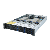
| Chassis type | Rack (2U) |
| Fan diameter | 80 mm |
| Product color | Black |
| Number of fans | 4 fan(s) |
| Memory channels | Octa-channel |
| Number of DIMM slots | 32 |
| Supported memory types | DDR4-SDRAM |
| Maximum internal memory | 128 GB |
| Supported RDIMM clock speeds | 2933, 3200 MHz |
| On-board graphics card model | Aspeed AST2500 |
| LAN controller | Intel® I350-AM2 |
| Ethernet LAN data rates | 10, 100, 1000 Mbit/s |
| Ethernet interface type | Fast Ethernet, Gigabit Ethernet |
| Storage drive sizes supported | 2.5, 3.5 \ |
| Supported storage drive types | HDD & SSD |
| Number of storage drives supported | 14 |
| Supported storage drive interfaces | Serial ATA III, Serial Attached SCSI (SAS) |
| PCI Express x8 slots | 6 |
| PCI Express x16 slots | 3 |
| PCI Express slots version | 4.0 |
| PCI Express x8 (Gen 3.x) slots | 1 |
| USB 2.0 ports quantity | 0 |
| USB 3.2 Gen 1 (3.1 Gen 1) Type-A ports quantity | 4 |
| Power supply | 1200 W |
| Input current | 7 - 12 A |
| AC input voltage | 100 - 240 V |
| AC input frequency | 50 - 60 Hz |
| 80 PLUS certification | 80 PLUS Platinum |
| Package depth | 588 mm |
| Package width | 982 mm |
| Package height | 268 mm |
| Package weight | 25500 g |
| Sustainability certificates | RoHS |
| Storage temperature (T-T) | -40 - 60 °C |
| Operating temperature (T-T) | 10 - 35 °C |
| Storage relative humidity (H-H) | 20 - 95 % |
| Operating relative humidity (H-H) | 8 - 80 % |
| Depth | 730 mm |
|---|---|
| Width | 438 mm |
| Height | 87 mm |
| Weight | 18000 g |