Do you have a question about the Gigabyte WATER FORCE and is the answer not in the manual?
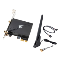
Details the components included in the trunk, covered with tearable plastic wrap, for the Water Force installation.
Open the trunk, take out the Water Cooling Box, and place it on the computer chassis using pins for stabilization.
Open the top and front covers of the Water Cooling Box and remove the first drive bay cover from the computer chassis.
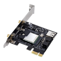
Connect the USB to the motherboard and the power connector to the power supply module for the Water Cooling Box.
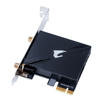
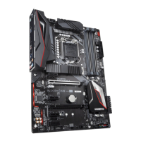
Install graphics cards into PCI-E slots and radiators through the chassis drive bay, securing pipes with clamps.
Place radiators into the Water Cooling Box and embed the pipes into the designated pipe slots for proper routing.
Close the top cover and front cover of the Water Cooling Box, ensuring power cables and water pipes are stored neatly.
Insert the CD-ROM BOX into the drive bay, extending its arm if necessary for a secure fit to the structure.
Connect VGA cards with power cables, use VGA JACK for support, link cards with SLI BRIDGE, close chassis, and install software.
| Connector | 4-Pin PWM |
|---|---|
| Warranty | 3 years |
| Type | Liquid Cooler |
| Radiator Size | 360mm |
| Fan Size | 120mm |
| Compatibility | Intel LGA 1200, 115x, 2066, 2011(-3); AMD Socket AM4 |