- 31 -
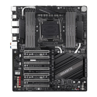
12) LED_C1/LED_C2 (RGB (RGBW) LED Strip Headers)
Theheaderscanbeusedtoconnectastandard5050RGB(RGBW)LEDstrip(12V/G/R/B/W),withmaximum
powerratingof2A(12V)andmaximumlengthof2m.
Before installing the devices, be sure to turn off the devices and your computer. Unplug the power
cord from the power outlet to prevent damage to the devices.
For how to turn on/off the lights of the LED strip, refer to the instructions in Chapter 5, "Unique
Features,""APPCenter\RGBFusion."
F_USB30
F_U
B_
F_ F_
_
B
BS_
B
SB_
B
_S
S_
_
B
_U
_
B
S
123
123
123
123
1
1
1
1
BSS
S
_S
SSU
1 2 3
S3
BSSS
U
__ 3
F_USB3F
S _
S _
S _
SF
B_
B_
F
_0
S
S
_0F
_F
_
_
__B
U
S _S
_
USB0_B
B_
F_USB3
_
1
F_USB30
F_U
B_
F_ F_
_
B
BS_
B
SB_
B
_S
S_
_
B
_U
_
B
S
123
123
123
123
1
1
1
1
BSS
S
_S
SSU
1 2 3
S3
BSSS
U
__ 3
F_USB3F
S _
S _
S _
SF
B_
B_
F
_0
S
S
_0F
_F
_
_
__B
U
S _S
_
USB0_B
B_
F_USB3
_
1
LED_C2
LED_C1
Pin No. Denition
1 12V
2 G
3 R
4 B
5 W
ConnectyourRGB(RGBW)LEDstriptotheheader.Thepowerpin
(markedwithatriangleontheplug)oftheLEDstripmustbeconnected
toPin 1 (12V) ofthis header.Incorrect connectionmay lead to the
damage of the LED strip.
RGBW
LED Strip
1
12V
RGB
LED Strip
1
12V
13) SATA3 0/1/2/3/4/5/6/7 (SATA 6Gb/s Connectors)
The SATA connectors conform to SATA 6Gb/s standard and are compatible with SATA 3Gb/s and SATA
1.5Gb/s standard. Each SATA connector supports a single SATA device. The Intel
®
ChipsetsupportsRAID0,
RAID1,RAID5,andRAID10.RefertoChapter3,"ConguringaRAIDSet,"forinstructionsonconguring
aRAIDarray.
7
1
7
1
SATA3
7 5 3 1
6 4 2 0
To enable hot-plugging for the SATA ports, refer to Chapter 2, "BIOS Setup," "Peripherals\SATA
AndRSTConguration,"formoreinformation.
Pin No. Denition
1 GND
2 TXP
3 TXN
4 GND
5 RXN
6 RXP
7 GND
 Loading...