EasyManua.ls Logo

GIGAIPC QBi-6412A User Manual

GIGAIPC QBi-6412A
58 pages
To Next Page IconTo Next Page
Page #1 background imageLoading...
Page #1 background image
1
www.gigaipc.com
QBi Series - 10” x 10” Embedded Compact Board QBi-6412A(MEHLJAH)
QBi-6412A (MEHLJAH)
10” x 10” Embedded Compact Board
Users Manual 1st Ed
Question and Answer IconNeed help?

Do you have a question about the GIGAIPC QBi-6412A and is the answer not in the manual?

GIGAIPC QBi-6412A Specifications

General IconGeneral
BrandGIGAIPC
ModelQBi-6412A
CategorySingle board computers
LanguageEnglish

Summary

Copyright Notice

Acknowledgement

Packing List

About this Document

Safety Precautions

FCC Statement

China RoHS Requirements (CN)

China RoHS Requirement (EN)

Chapter 1 - Product Specifications

1.1 Specifications- QBi-6412A (MEHLJAH)

Detailed technical specifications of the QBi-6412A motherboard.

Chapter 2 - Hardware Information

2.1 Jumpers and Connectors Overview

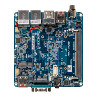
Visual guide to the location of jumpers and connectors on the board.

2.2.1 SYS_PANEL (Front panel header)

Pinout details for the front panel connection.

2.2.2 M2E (M.2 Slot, E-Key NGFF 2230)

Pinout details for the M.2 E-Key slot.

2.2.3 FUSB2_1, FUSB2_2 (USB 2.0 header)

Pinout details for USB 2.0 headers.

2.2.4 BATTERY (Battery connector)

Pinout details for the battery connector.

2.2.5 ATX_IN (ATX IN Connector)

Pinout details for the ATX power connector.

2.2.6 SODIMM (DDR4 SO-DIMM Slot)

Identifies the memory slot location.

2.2.7 SATAIII (SATA 6 Gb/s connector)

Pinout details for the SATA data connector.

2.2.8 SATA_PWR (SATA power connector)

Pinout details for the SATA power connector.

2.2.9 M2M (M.2 Slot, M-Key NGFF 2280)

Pinout details for the M.2 M-Key slot.

2.2.10 CPU FAN (CPU Fan connector)

Pinout details for the CPU fan header.

2.2.11 USB32_2 (USB 3.2 Gen 2x1 connector)

Pinout details for a USB 3.2 Gen 2x1 connector.

2.2.12 COM (Serial port connector, RS-232)

Pinout details for the serial port connector.

2.2.13 DC_IN (Screw type DC Jack connector)

Identifies the DC power input jack.

2.2.14 USB32_1 (USB 3.2 Gen 2x1 connector)

Pinout details for another USB 3.2 Gen 2x1 connector.

2.2.15 HDMI_21 (HDMI connector)

Pinout details for the HDMI connector.

2.2.16 LAN1, LAN2 (LAN connector)

Details for LAN connectors, including LED status.

Chapter 3 - BIOS Configuration

3.1 BIOS Introduction

Overview of the Basic Input/Output System functionality.

3.2 The Main Menu

Displays system information and basic settings.

3.3 Advanced BIOS Settings

Access to detailed hardware configuration options.

3.3.1 TPM Configuration

Settings for Trusted Platform Module (TPM) functionality.

3.3.2 S5 RTC Wake Settings

Configures system wake-up events from S5 state.

3.3.3 CPU Configuration

Settings related to CPU features and performance.

3.3.4 SATA Configuration

Settings for SATA storage controllers and devices.

3.3.5 IT8613 Super IO Configuration

Configuration for the IT8613 Super I/O chip functions.

3.3.6 Hardware Monitor

Displays system sensor data like temperature and fan speed.

3.3.7 AMI Graphic Output Protocol Policy

Controls the primary graphics output.

3.3.8 Network Stack Configuration

Settings for network boot features like PXE.

3.3.9 NVMe Configuration

Configuration for NVMe storage devices.

3.3.10 Offboard SATA Controller Configuration

Configuration for additional SATA controllers.

3.4 Chipset Settings

Settings for various chipset features.

3.5 Security Settings

Options for system security, passwords, and Secure Boot.

3.6 Boot Options

Configuration of system boot behavior and priorities.

3.7 Save & Exit BIOS

Options to save changes or exit the BIOS setup.