16. The fuel injector control circuit is efficient. While the engine is running, the opening time of the fuel
injector can be displayed through the indication given in the "PARAMETERS" menu of the scooter
diagnostic tester.
T. FUEL INJECTION (mS) =
about 6 mS (start-up at 20°C)
about 1.8 mS (idle at 20° C)
about 1.6 + 1.5 mS (idle at 60° C)
The values are indicative but useful for diagnostics. Command failures or unusual opening times are
always caused by the ECU.
Specific tooling
020460Y Scooter diagnosis and tester
coolant temperature sensor circuit
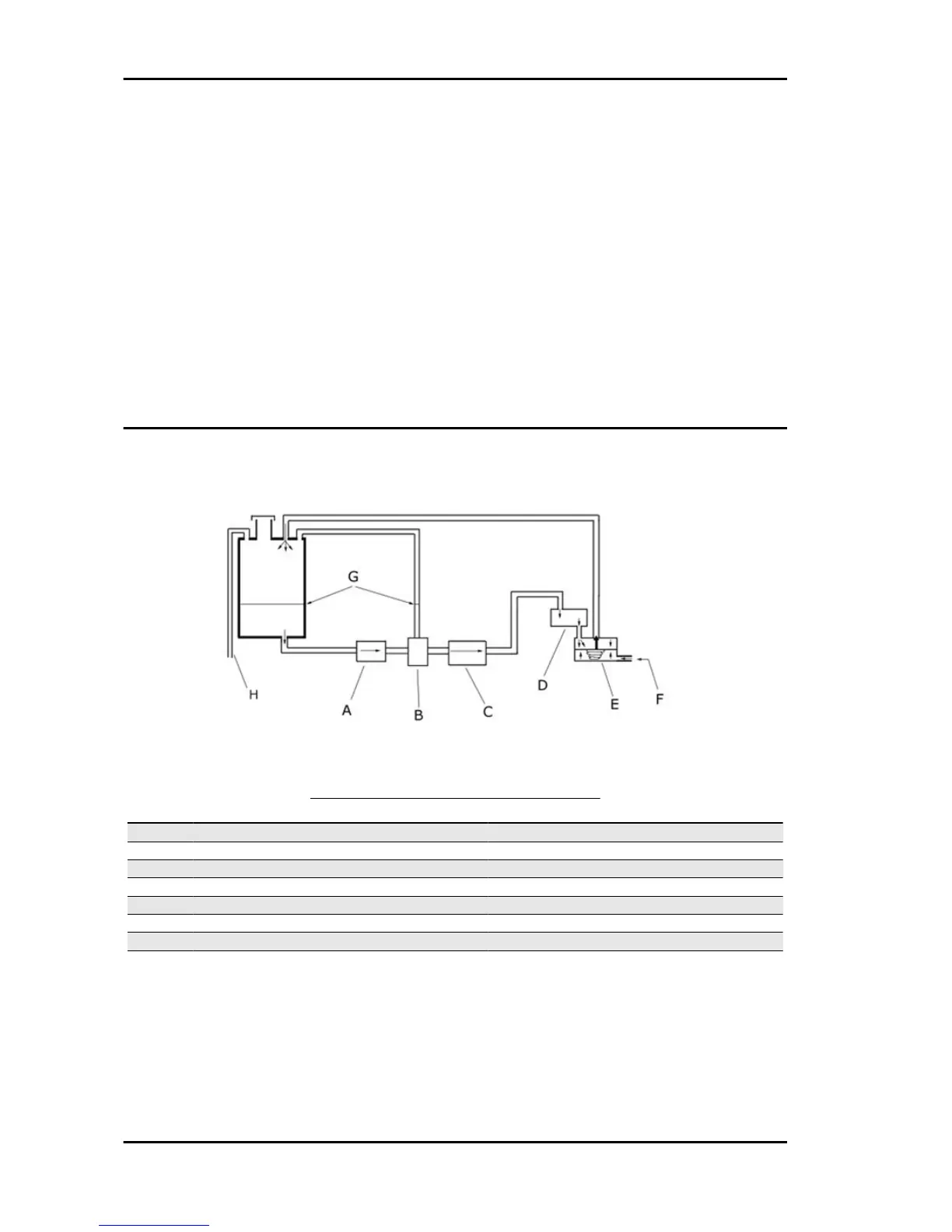
DIAGRAM OF FUEL SUPPLY SYSTEM
Specification Desc./Quantity
1 Fuel filter
2 Shunt
3 Fuel supply pump
4 Injector
5 Pressure regulator
6 Compressed air inlet
7 Fuel level
8 Tank ventilation
The first section of the fuel supply system on the fuel injection version of the Runner consists of an
outlet fitting located in the lower half of the tank. Fuel flows through the transparent-type paper filter and
to the shunt, just before the pump. The shunt is attached to the bleed tube leading to the upper-half of
the tank. The principle of communicating reservoirs guarantees the bleeding of the pump intake right
from the first refill. The pump must not be started before the tank has been filled. Failure to comply with
this rule may result in seizure of the pump. The fuel pump is installed at an angle so to improve the
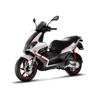
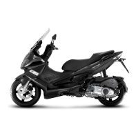
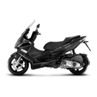
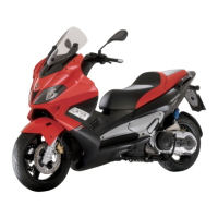
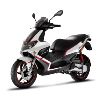
pure jet injection Runner RST Purejet
INJ PJ - 54



 To Next Page