Electrical System
367
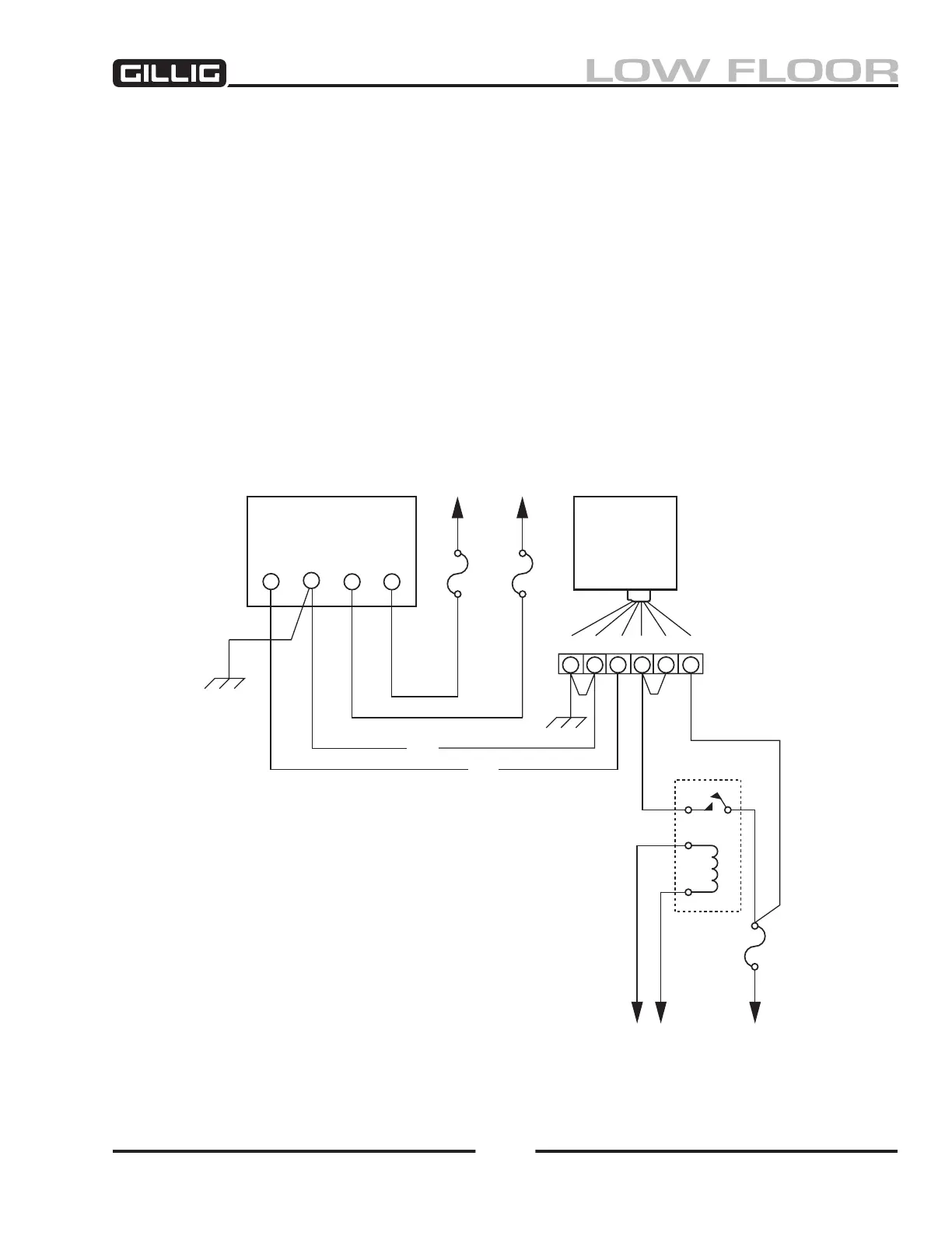
Figure 9-12, Charging System Schematic
8. Connect voltmeter to regulator POS terminal. This is the input voltage to the regulator.
a. If voltmeter reads 24–28 volts and voltage in Step 7 was less than 28 volts and the ground
connection (Step 6) is good, the regulator is defective.
b. If the voltmeter reads 0 or less than 24–28 volts, proceed to the next step.
9. Move to the ignition relay and connect the voltmeter to terminal 87.
a. If voltmeter reads 24–28 volts, there is a problem in the wiring between the alternator POS
terminal and the ignition relay.
b, If voltmeter reads 0 volts, proceed to next step.
10. Connect voltmeter to ignition relay terminal 30. This is the 24 volt input.
a. If voltmeter reads 24–28 volts, ignition relay is not energized. This relay is energized by I/O
controls. Refer to ladder charts in Multiplex Schematics.
b. If voltmeter reads 0 volts, check fuse, then troubleshoot 24 volt input circuit wiring.
ALTERNATOR
FUSE
325A
FUSE
9A
FUSE
9A
REGULATOR
BREAK-OUT TOOL
(Do Not Pierce
Wire Insulation)
F1 F2 POS RELAY
GND
GRN
RED
FLDGNDGND
IGN BATT
SENSE
24V
BATTERY
24V
BATTERY +
TO
NO-CHARGE
RELAY
FROM
I/O CONTROLS
IGNITION RELAY
87
30
621543
 Loading...