Electrical System
391
Module LED’s
The multiplexing system modules have LED indicator lights to help you nd problems. Observing the
LED’s on the modules while referring to the ladder chart for your bus will enable you to solve most
electrical problems on the bus.
Input Circuits
Input circuits have green LED’s. Refer to the input/output map for your coach to determine which circuit
a particular LED is monitoring. On T2-DIO-888, T2-HCNC-888, and T2-DIO-808S modules, input cir-
cuits are always numbered 17 through 24. On the T2-DIO-168S-K7 LED’s 9–24 indicate inputs.
Output Circuits
Output circuits are monitored using the red or amber LED’s. Refer to the input/output map for your
coach to determine which circuit a particular LED is monitoring. Red LED’s are assigned a circuit num-
ber. When a red LED lights up, it indicates that the output circuit is on or active. On T2-DIO-888, T2-
HCNC-888, and T2-DIO-808S modules, output circuits and their corresponding red LED’s are always
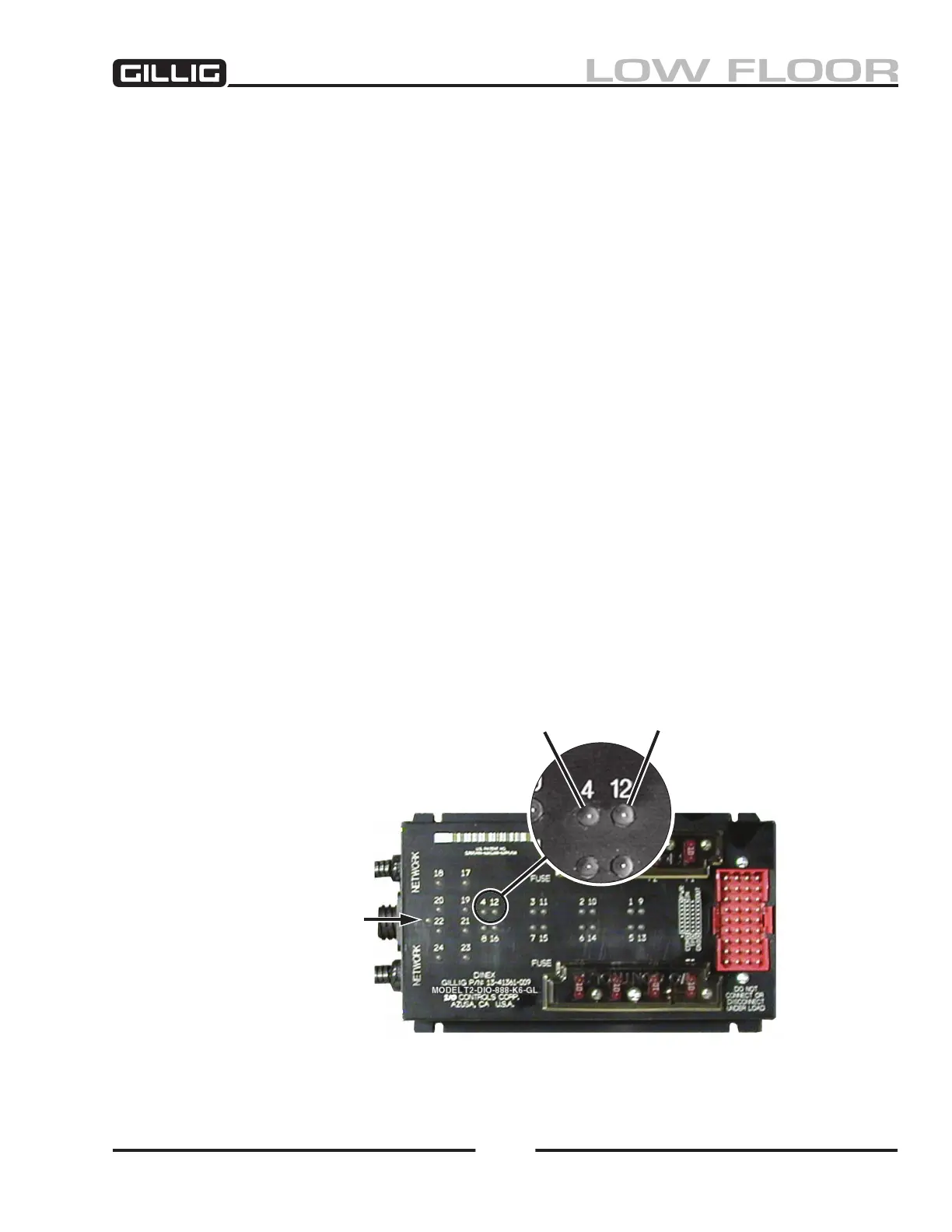
numbered 1 through 8. T2-DIO-888 and T2-HCNC-888 modules have amber output LED’s in addition
to the red LED’s; the amber LED’s indicate that a circuit is ready but not active. Each amber LED is
paired with a red LED (see Figure 9-39); the circuit number being monitored is the one by the red LED.
The number assigned to each amber LED is the circuit number plus 8.
Data Communication Status LED
On the left side of each module (except the T-PMS-0025 power supply) will be one or two unlabeled red
LED’s. See Figure 9-39 for location. The Data Communication Status LED’s indicate communication
with other modules. If there are two Data Communication LED’s on a module, they will be labeled with
ID numbers so you can tell which group of circuits each is monitoring.
Data Communication
Status LED
(red)
Figure 9-39, Multiplex Module LED’s
Output circuit
active
LED (red)
Output circuit
ready
LED (amber)



 To Next Page