Body and Interior
481
Manual Insertion
The locking strip can be manually inserted by using a at blade screwdriver or similar tool. Liberally
lubricate the locking strip lip. Push the at bladed tool along the molding, turning the blade sideways to
spread the groove open while pushing the strip into the groove with your thumb. When using this meth-
od it is essential to make sure that even tension is applied to the strip and that the locking strip is forced
completely into the molding groove.
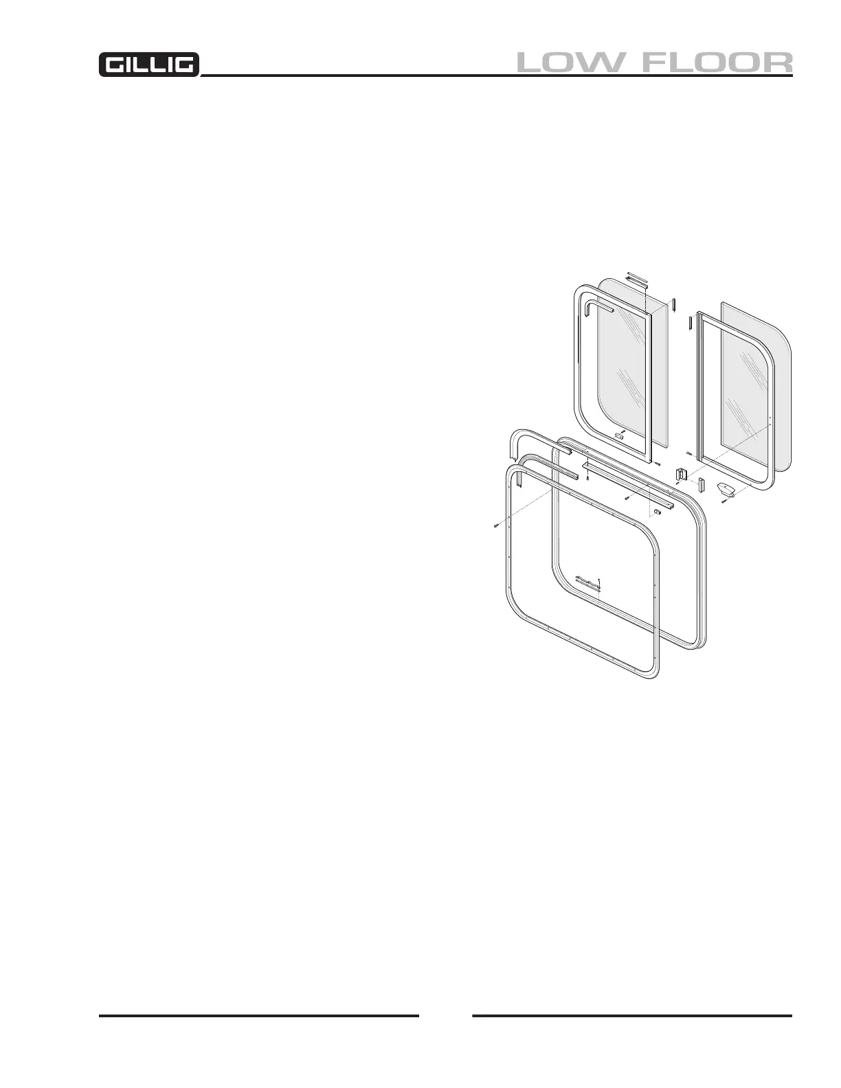
Driver’s Side Window
The dual slider window (Figure 11-30) allows the
driver maximum exibility to signal or conduct other
operations while in the driver’s seat. The windows are
individually framed and enclosed in a one-piece anod-
ized aluminum frame with slide rails fabricated into the
frame. The inner frame around each window has a cen-
ter slot rimmed with brush trim on each side to facilitate
sliding without lubrication. The window unit comes
complete with all required rubber insulation molding
fabricated into the frame.
Latches
The slider window has a latch for opening and closing.
On the dual slider, the latches are positioned toward
the outer frame side of the glazing panel; i.e., on the
right side of the right glazing and on the left side for the
left glazing. Latches are operated by pressing the latch
handle towards the glazing to disengage the latch, then
pushing or pulling the handle in the appropriate direc-
tion to slide the glazing panel.
A latch is removed by unscrewing the two Phillips head
screws which secure the latch to the frame. To replace
the latch, reposition the latch and screw into place.
Figure 11-30, Driver’s Dual Slider
Window (Typical)
 Loading...