EasyManua.ls Logo

GISMA 10 Series - Mounting Dimension

GISMA 10 Series
44 pages
To Next Page IconTo Next Page
To Previous Page IconTo Previous Page
Loading...
Handling instructions
for GISMA connectors
HI 2007 - 001
Document: replaces
MV 2000-020,
MV 2000-030 and
MV 2005 - 011
First issue: 15.07.2008
Rev.-Index: -Z-
From: 29.07.2020
Copyright by:
GISMA GmbH
Page 18 of 44
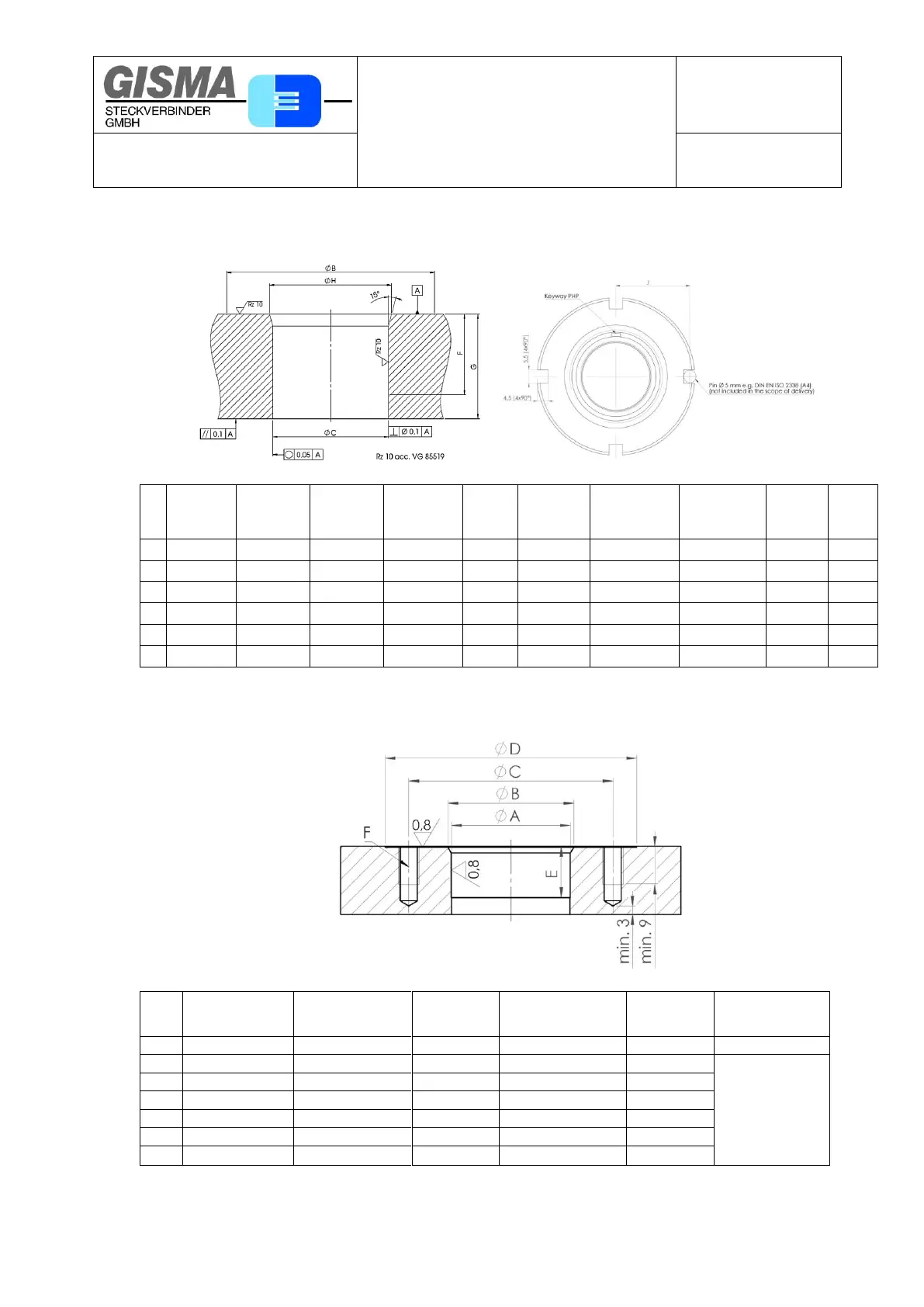
7.3.6. Mounting dimension
Mounting hole for pressure hull penetrator
Size
Ø B
min.
Ø C
O-ring sealing
(acc VG
85519)
Ø C
Profile
sealing ring
Ø C
Alternatives
tolerances o-
ring profil
sealing
F
min.
G
Standard PHP
20.04.x...
G
Bothsides
pressure
watertight PHP
20.54.x...
G
Bothsides
pressure
watertight PHP
20.64.x...
Ø H
J
DIN
7168
middle
1
70
39
±0,05



39
H7/H8
27
40-85
40-90
/
41,1
+1
30,4
2
70
39
±0,05



39
H7/H8
27
40-85
40-90
/
41,1
+1
30,4
3
70
39
±0,05



39
H7/H8
27
40-85
40-90
26-43
41,1
+1
30,4
4
85
54
±0,05



54
H7/H8
26,5
40-85
/
27-43
56,1
+1
37,9
5
85
54
±0,05



54
H7/H8
28
40-85
/
27-43
56,1
+1
37,9
7
105
72
±0,05



72
H7/H8
33,7
40-85
/
/
74,1
+1
47,4
Mounting holes for standard pressure hull penetrators. Please, contact our design department for special ones!
Mounting hole for flange-receptacle
Size
Ø A
Ø B
Ø C
max
Ø D
Ø E
min
Ø F
0
22
±0,05
23
-0,3
38,5
49
12
M5 (4x90°)
1
26
±0,05
28
-0,3
50
63
11
M6 (6x60°)
2
32
±0,05
34
-0,3
56
69
9
3
35
±0,05
37
-0,3
60
73
9
4
47
±0,05
49
-0,3
71
84
9
5
56
±0,05
57
-0,3
74
87
11
7
72
±0,05
74
-0,3
102
115
16
Mounting holes for standard pressure hull penetrators. Please, contact our design department for special ones!

Table of Contents

Related product manuals