Handling instructions
for GISMA connectors
HI – 2007 - 001
Document: replaces
MV 2000-020,
MV 2000-030 and
MV 2005 - 011
First issue: 15.07.2008
Rev.-Index: -Z-
From: 29.07.2020
Page 42 of 44
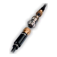
De-Mating
De-mating is achieved by a straight pull on the ROV handle sufficient to release the latching
mechanism.
Cathodic Protection
Stainless steel (1.4404/ 1.4571 comparable to 316L/316Ti) or titanium grade 5 stab plate
connectors must be connected to the CP (Cathodic Protection) system at all times. If the
connector is designed with a fixed flange and screw mounting, an additional CP connecting
would not be required. Super Duplex stainless steel connectors should be isolated from the
CP system to reduce the possibility of hydrogen embrittlement.
Mating forces (standard configuration)
Mating forces
for contact-Ø 3mm
Table: Mating and de-mating forces for ROV connectors
 Loading...