- 3 -
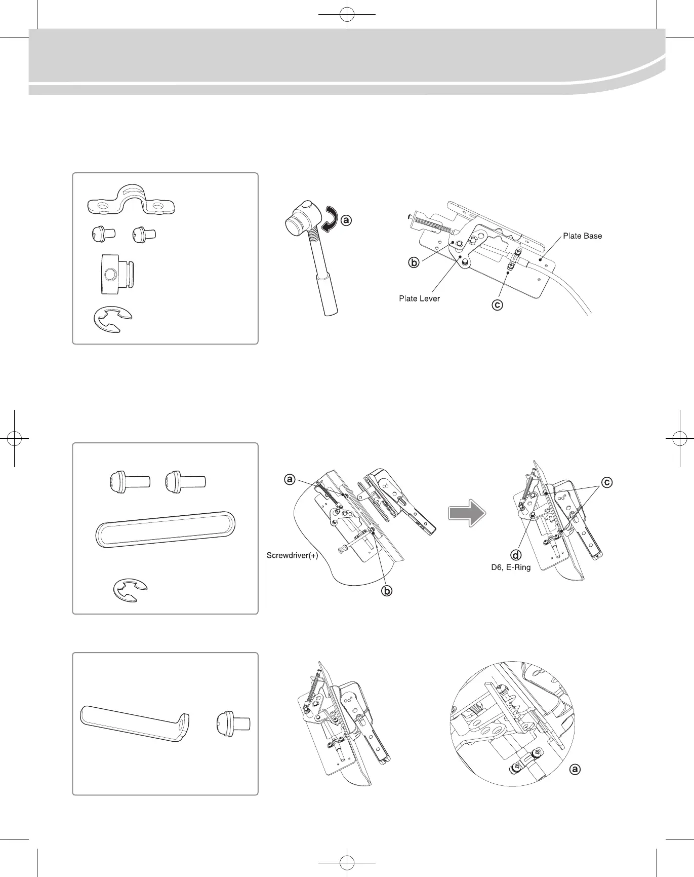
3. How to couple Plate Flange Ass’y and Cable cylinder
Connect Drive Shaft that is inside the plastic bag rotating it as ⓐ so that the end of Cable cylinder screw sticks out 2~3mm.
Place Plate Lever in Ø10 slot and connect it as ⓑ to D8,E-Ring. Adhere Cable cylinder on Plate Base’s front side along with Cable Holder as ⓒ
using M5X10 Screw(2ea).
4. How to connect Plate Flange Ass’y and Handle to Enclosure
Place Rubber Ring in the slot of Handle Ass’y. Adhere it to Enclosure’s upper part.
Place Plate Flange Ass’y in the slot and attach M6X18 loosely as ⓐ.
Tighten loosely M6X18 as ⓑ in the lower side. Find the balance of Handle Ass’y moving it up-down, right-left, then as ⓒ, tighten completely
Screw from the upper side with the one from the lower side. Move Handle in ON-OFF direction in order to make Link Hole of Handle Ass’y
match with Lever Pin as ⓓ, and connect D6, E-Ring. Check the movement of the Handle by switching it On and Off.
5. Place Door Lock’s component in the slot of Release Lever as ⓐ and tighten M6X10 Screw.
Cable Holder
M5X10, Screw
Drive Shaft
E-Ring, D8
M6X18, Screw
E-Ring, D6
Door lock M6X10, Screw
Rubber Ring
Installation Instruction
GCB100
(GCBX1-FHC-N3R4-M/GCBX1-FHC-N4X-M)