3.0 SAFETY
3.1 GENERAL SAFETY
6
© Dimplex Boilers 2008
It is the law that all gas appliances are installed by a competent
person in accordance with the above regulations. Failure to
install appliances correctly could lead to prosecution. It is in
your own interest, and that of safety, to ensure that the law is
complied with. If the appliance is damaged, turn off the
appliance and consult a CORGI registered engineer. If it is
known or suspected that a fault exists on the appliance it
be used until the fault has been rectified by a
competent person.
DO NOT interfere with any sealed components and use the
appliance only in accordance wi
This appliance is not intended for use by persons (including
children) with reduced physical, sensory or mental capabilities,
or lack experience and knowledge, unless they have been given
supervision or instructions concerning use of the appliance by
a person responsible for their safety. Children should be
supervised to ensure that they do not play with the appliance.
3.2 CURRENT GAS SAFETY (INSTALLATION & USE) REGULATIONS
This appliance must be earthed.
Supply: 230V - 50Hz fused at 3A.
The method of connection to the mains supply must facilitate
complete isolation of the appliance. Either a 3A fused three pin
plug and unswitched shuttered socket outlet, or a 3A fused
double pole switch having a 3mm contact separation in both
poles, serving only the boiler (and its external controls), may
be used.
1. A flat vertical area is required for the installation of the
boiler.
2. Where an open flued (B23) system is used then an air vent
must be provided in the same room or internal space of the
flue duct air inlet, with a minimum free area of:
Dimplex 24 = 88cm
2
Dimplex 30 = 121.5cm
2
Dimplex 38 = 159cm
2
3. These dimensions include the necessary clearance around
the boiler for case removal, spanner access and air movement.
Additional clearances may be required for the passage of pipes
around local obstructions such as joists running parallel to the
front face of the boiler.
4. When installed in a cupboard or compartment it is not
permissible to store other objects in the cupboard. Additionally
no flammable objects/items must be allowed to come into
contact with the boiler.
5. The boiler does not require additional ventilation when it is
installed in a cupboard or compartment. The exception to this
is where an open flue system has been installed - See note
3.4.2.
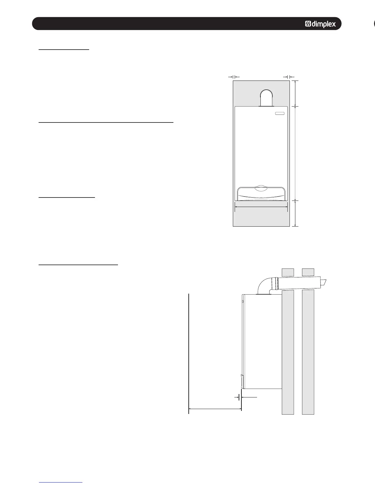
Clearances
Clearances
3.4 CLEARANCES AND VENTILATION
5mm Min
446mm
5mm Min
796mm
200mm
200mm
285mm Wall
450mm Min
For Servicing
Purposes
5mm Min
In Operation
1.2 SYSTEM PRESSURE GAUGE
The normal operating water pressure is shown when the
needle is in the GREEN section of the gauge between 1 and 2
bar.
If the pressure drops too low the system will need topping up
via the filling loop.
If the pressure exceeds 3 bar the pressure relief valve will
operate and a fault may be indicated. Contact your installer
(see section 1.9).
Red
Red
Green
Clock - Arrow indicates current time
Tabs in - OFF Period
Tabs out - ON Period
Clock Override Switch 1 - On Continuously
Mid-Position - Timer Central Heating
0 - Off - No Central Heating
1.4 CH - CENTRAL HEATING TEMPERATURE CONTROL
Switch shown in the OFF position.
Turn the knob clockwise to increase the temperature of the
central heating.
min = 30°
max = 80°
1.5 DHW - DOMESTIC HOT WATER TEMPERATURE CONTROL
Switch shown in the OFF position.
Turn the knob clockwise to increase the temperature of the
domestic hot water.
min =
1.3 CENTRAL HEATING TIME CLOCK
1
13
2
14
3
15
4
16
5
17
6
18
7
19
8
20
9
21
10
22
1
1
23
12
24
0
1
Tabs
Current Time Arrow
Clock Override Switch
Comfort +
1
13
2
14
3
15
4
16
5
17
6
1
8
7
19
8
20
9
21
10
22
11
23
12
24
0
1
0
1
2
bar
3
4
System Pressure Gauge Central Heating
Time Clock
Central Heating
Temperature Control
Display and Indicator
Lights
Domestic Hot
Water
Temperature Control
Fig. 2
Fig. 3
Fig. 4
Fig. 5
Fig. 6
 Loading...

