HARDWARE SETUP
NOTE: Numbers to the left correlate with associated numbered step below:
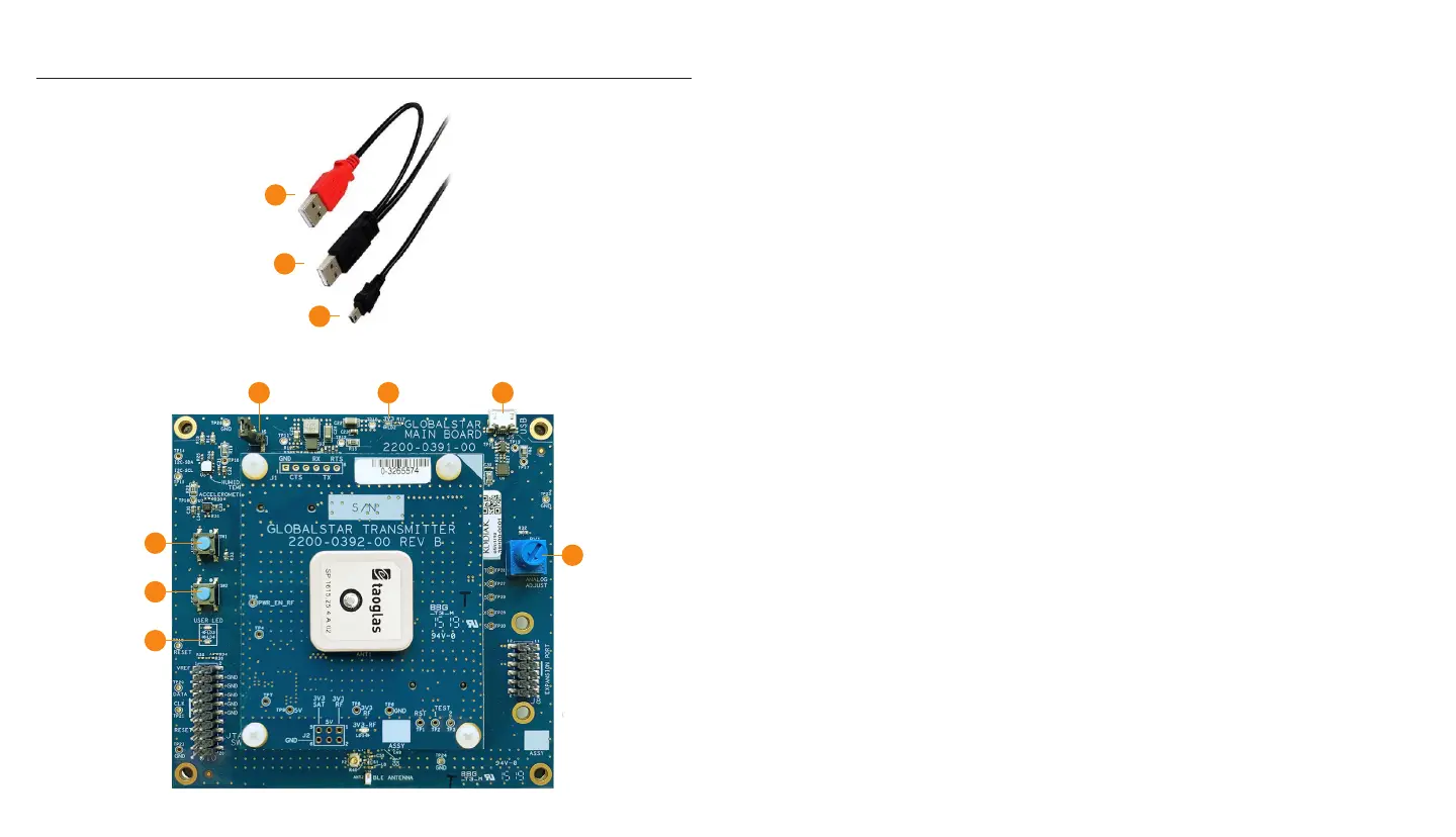
1. Remove the STX3 Dev Kit from the electrostatic safe bag.
2. Connect the red USB (2) connection of the USB Y-Cable into a USB port on your PC
or laptop.
3. Connect the black USB (3) connection of the USB Y-Cable into a second USB port on
your PC or laptop.
4. Connect the mini-USB (4) into the Dev Kit.
• Upon power up, the 3V3 LED (LD2) will illuminate continuously indicating
power is applied.
• Also, the USER LEDs (LD3 & LD4) will light up and blink momentarily.
5. Confirm that the 3V3 LED LD2 (5) is illuminated indicating power is applied.
6. Confirm the USER LED LD4 (6) has started to pulsate.
7. User button SW1 (7) is configured by default to send the STX3 test packet as a
standard data message. Pressing it will queue the message and illuminate USER LED
LD3 red until all bursts are sent.
8. Button SW2 (8) will perform a soft power reset of the nRF52 processor.
a. NOTE: If a hard power reset of the whole Dev Kit is needed, the jumper J6 can
be connected to pull the input supply voltage to ground.
9. Analog Adjust Potentiometer RV1 (9) can be used to adjust the output voltage read by
the on-board ADC.
4
3
2
6
8
7
5
8a
4
9
 Loading...