MAR 2018 GFV-305 (Formerly H-3) Page 2 of 11
MODEL RCW DRY SYSTEM
The dry system trim is one optional trim arrangement for
the Globe Model RCW valve. This arrangement is typically
utilized when the system is subject to areas exposed to
freezing or close to freezing temperatures. With this con-
guration, the detection system consists of automatic sprin-
klers spaced throughout the protection area. System air
pressure is used to ensure the integrity of the system piping
and used as the activation method for the valve.
Water pressure is maintained in the valve pressure chamber
up to the dry pilot actuator through a restricted connection
from the main water supply which is taken upstream of the
system main control valve (The pressure chamber supply
valve must remain in the open position at all times when the
system is in service). The dry pilot actuator is normally held
in the closed position by the system air pressure supplied
through the automatic air or nitrogen maintenance device.
When an automatic sprinkler operates, the air ow rate
through the open sprinkler is at a ow rate greater than that
which can be supplied through the automatic air or nitrogen
maintenance device. This causes a pressure drop in the
system and the upper chamber of the dry pilot actuator. An
optional accelerator can increase the rate at which the air
decays on the dry pilot actuator, if a faster time to trip the
Model RCW valve is required.
Once the pressure in the upper chamber of the dry pilot
actuator drops sufciently, the upper chamber can no lon-
ger hold the diaphragm in the closed position. The dry pilot
actuator opens and allows water to ow from the pressure
chamber to the drain at a ow rate greater than that which
can be supplied through the restriction in the pressure
chamber supply line. The opening of the dry pilot actuator
results in a drop in pressure in the pressure chamber and
the Model RCW valve operates (trips) allowing water to ow
into the system piping. The automatic actuation of the fea-
ture of the valve can be bypassed by manually rotating the
handle on the "Manual Control/ Emergency Release" valve
located on the Model RCW trim to activate the Model RCW
valve.
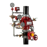
Note:
See recommended system air/nitrogen pressure and expected trip range below
for the Model GDPA. More detailed information can be found about the Dry
Pilot Actuator in Technical Data Sheet GFV550.
GDPA VS GDPA-LP
When choosing the dry pilot actuator for your system
there are many factors which inuence the uid deliv-
ery time. These factors range from system geometry,
riser location, sprinkler orice size, supply pressure,
pump ramping time and more. In certain systems,
higher system air pressure can be advantageous over
lower system air pressure and the opposite can also
be true. Some things to consider when choosing the
GDPA vs the GDPA-LP are discussed below.
The initial air pressure in a system may vary. For ex-
ample in one system the initial air pressure may be set
for 15 psi (1 Bar) and 45 psi (3.1 Bar) for the other. The
system air pressure will decay at a faster rate with the
higher initial system pressure. For a xed pressure
drop (i.e. 5 psi drop) will be reached more quickly with
the higher initial air pressure than lower initial air pres-
sure.
Unfortunately uid delivery time is not just dependent
on tripping the control valve but also dependent on
the uid moving through the system. As the water lls
the system piping it can create a high pressure pocket
of air at the inspectors test connection. This higher
air pressure can slow the progress of the water pro-
gressing towards the inspectors test connection. This
phenomenon typically happens with smaller K-factor
sprinklers. This scenario may lend itself to choosing
to utilize lower system air pressure and the GDPA-LP
actuator.
In other circumstances, systems are center fed, mean-
ing roughly half of the volume of piping is on one side
of the riser and half on the other. In these scenarios,
higher system air pressure can be benecial to system
delivery time as the higher air pressure will actually im-
pede or stop the propagation of water in the direction
opposite the inspectors test connection (ITC) and force
the majority of the available water ow towards the ITC.
It would be impossible to run through every scenario
possible but there are a few generalities which can
be used as guidance. Generally end fed systems will
achieve faster uid delivery times with lower air pres-
sure. Generally center fed systems with moderate to
better than moderate water supplies will have faster
FIGURE 1:MODEL GDPA DRY PILOT
TRIP RANGE
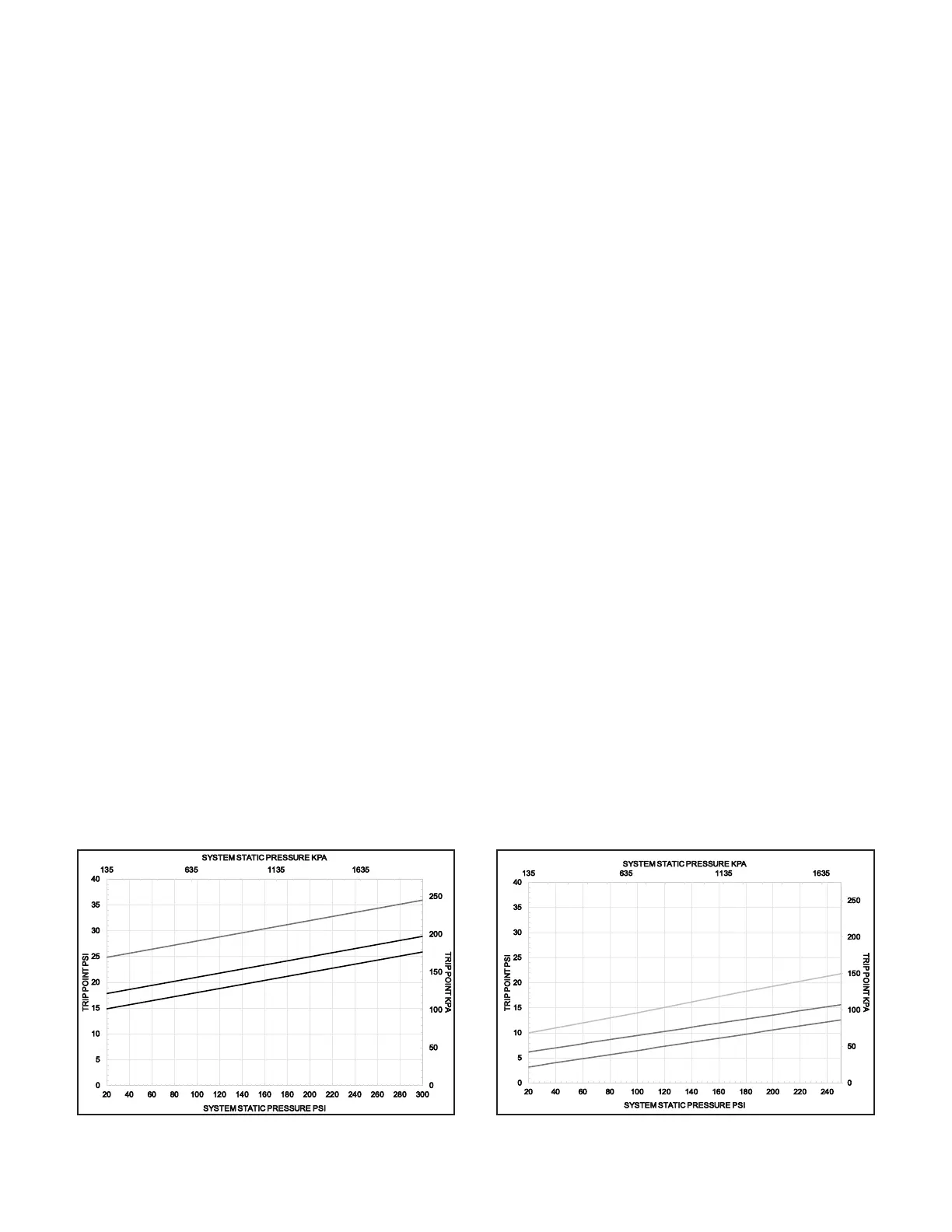
FIGURE 2:MODEL GDPA-LP DRY
PILOT TRIP RANGE
GDPA-LP Trip Range
Recommended Air/Nitrogen Pressure
Recommended Air/Nitrogen Pressure
GDPA Trip Range
 Loading...