MAR 2018 GFV-305 (Formerly H-3) Page 8 of 11
INSTALLATION AND MAINTENANCE
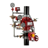
INSTALLATION
Proper operation of the RCW Valve (i.e., opening of the
RCW Valve as during a re condition) is highly dependent
on the correct installation of the trim. It is necessary to in-
stall the trim components as described in the gures above
for the valve to function properly. Failure to do so may
prevent the valve from functioning and could void Listings,
Approvals, and/or the manufacturer's warranty. All tubing
directed to the "drip cup" must have smooth bends. Abrupt
changes in direction or kinks in the tubing could result in a
restriction of ow and an adverse effect on the functionality
of the valve.
The Model RCW Valve must be installed in an accessible
and visible location, which is maintained at or above a mini-
mum temperature of 40ºF (4ºC). The RCW Valve must be
installed in the vertical orientation.
All valves must be installed in accordance with the appropri-
ate installation standard (i.e. NFPA 13, NFPA 15 or other).
All electrical connections must be made per the applicable
installation standard and/or the National Electric Code (i.e.
NFPA 70, NFPA 72 or other).
Proper hydrostatic test procedure must be followed per
NFPA 13. The velocity check valve must be replaced with a
plug temporarily, the pressure chamber must be vented dur-
ing the hydrostatic test procedure by opening the manual
release valve and the clapper must be latched in the open
position.
DRY VALVE SETTING
PROCEDURE
The following steps are to be followed for initial setting
of the Model RCW dry system valve, after a trip test of
the re protection system or, after any system opera-
tion.
STEP 1. Close the main control valve.
STEP 2. Close the pressure chamber supply control
valve and the system air supply valve.
STEP 3. Open the main drain valve, lower body (Aux)
drain valve, all low point drain valves and auxil-
iary drain valves on the system. Open the man-
ual emergency release control valve. Depress
the plunger of the velocity check valve to verify
that it is not under pressure and that the sys-
tem piping is completely drained. After system
is completely drained, close all low point and
auxiliary drain valves that are open. The man-
ual emergency release control valve and main
drain valve should remain open until directed in
the following steps.
STEP 4. Depress the reset plunger located at the top of
the pressure chamber to reset the clapper of
the RCW valve (the sound of the clapper fall-
ing into position should be heard). Close the
manual emergency release control valve.
STEP 5. Replace any operated automatic sprinklers
with the same type, i.e. orientation, orice, tem-
perature, and thermal sensitivity. Open the
air supply valve to re-establish normal system
pressure. Open the manual emergency release
control valve and then the pressure chamber
supply control valve. Slowly close the manual
emergency release control valve and allow
pressure to increase in the pressure chamber
and also up to the dry pilot actuator.
STEP 6. Observe all drain tubing at the drip cup. If any
leakage is observed, the source of the leakage
must be identied and corrected.
STEP 7. Partially open the main control valve. Slowly
close the main drain valve when water dis-
charges from the drain connection. Observe
the supply pressure gauge and the pressure
chamber gauge. They should indicate the same
pressure reading. Depress the plunger on the
velocity check valve. If leakage is apparent, the
cause of the leakage must be identied and
corrected. If there are no leaks, open the sys-
tem control valve fully and the system is set for
service.
MODEL C ACCELERATOR
SETTING PROCEDURE
STEP 1. Close the accelerator shutoff valve
STEP 2. Follow the Dry Valve Setting Procedure
STEP 3. Upon completion of the Dry Valve Setting Pro-
cedure. Open the accelerator shutoff valve
slowly. Watch the pressure gauge on the upper
chamber of the Model C Accelerator for 30 sec-
onds. The pressure should start to increase. If
the pressure increases and the accelerator sets
(no air coming from the discharge of the accel-
erator), wait for the upper chamber of the accel-
erator to reach the system air pressure and the
system is set for service. If the pressure does
not increase in 30 seconds continue to step 4.
STEP 4. Close the accelerator shutoff valve. Remove
the lower hand wheel plug. The accelerator in-
terior valve assembly should be removed. This
complete assembly can be pulled out by hand
(if it does not come out with the lower hand
wheel plug when it is unscrewed). This will
allow any water, that may have accumulated
in the upper chamber, to drain out and permit
thorough cleaning of the valve disc, seat as-
sembly, and the orice pin.
STEP 5. The valve assembly can then be replaced and
the lower hand wheel plug screwed back into
position. Open the accelerator shutoff valve
slowly. The accelerator is set for service when
the air pressure gauge on the top of the accel-
erator reads normal system air pressure. If air
pressure does not rise in the upper chamber of
the accelerator after 1 minute call Globe Tech-
nical Support for more detailed instruction.
TESTING
Reference NFPA 25, Standard for the Inspection, Testing
and Maintenance of Water-Based Fire Protection Systems.
Before proceeding with any tests involving water ow, the
following precautions need to be taken:
STEP 1. Check the location where the test connection
discharges to make sure that all is clear and
that there is no possibility of the water ow
causing damage or injury.
STEP 2. Check the end of the test connection to make
sure that it is unobstructed. To achieve a satis-
factory test, there must be an unrestricted ow
of water when the test valve is wide open.
STEP 3. Check for alarm connections to a central sta-
 Loading...