Supplied By www.heating spares.co Tel. 0161 620 6677
35
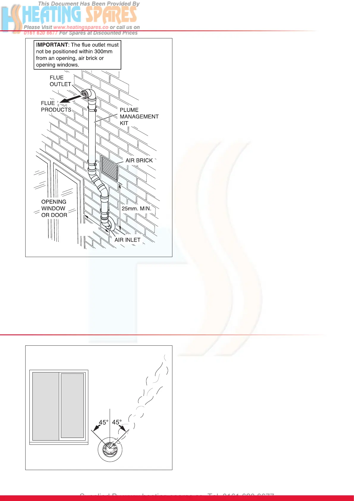
10 Plume Management Kit
10.13 Plume Management Kit
The Plume Management Kit: Part No. A2044100 (white) or
A2044000 (black) can be used to overcome many site issues.
The Plume Management Kit will t to the Top Horizontal
Telescopic, Rear Horizontal Telescopic and Standard
Horizontal Flue. This enables the ue products to exhaust
further away from the boiler, thereby reducing the impact of
pluming.
NOTE: The ue air inlet can be sited closer to doors, opening
windows and air bricks, than stated in section 4.2, see
diagram 10.28.
The maximum length of the Plume Management Kit must NOT
exceed 6m with a horizontal concentric ue length of 2m max.
For each 90
o
bend or 2 x 45
o
bends the maximum length of the
Plume Management Kit must be reduced by 1m.
For more information contact Glow-worm, refer to page 2.
The Plume Management Kit is supplied with installation
instructions.
Refer to BS5546 or BS6798 for advice on disposal of boiler
condensate.
150mm.
MIN.
12997
Diagram 10.28
10 Deector Flue Terminal Kit
Diagram 10.29
14465
10.14 Deector Flue Terminal Kit
The terminal kit ts onto the telescopic and standard
horizontal ue, see diagram 4.1 for kit contents.
The kit is also supplied with installation instructions.
NOTE: The deector ue terminal kit can be tted after the
boiler and ue have been installed.
The deector part of the deector ue terminal can be rotated
45º to allow pluming away from openings, people, cars,
windows etc., see diagram 10.29.
Should the deector terminal be positioned under a soft or
horizontal surface, it is allowed to project the ue 600mm from
the wall, to allow the discharge of ue gases produced into
free air.
IMPORTANT: Do not t the deector ue terminal with the
deector positioned downwards.