Supplied By www.heating spares.co Tel. 0161 620 6677
37
11.2 System Controls 24V
WARNING: UNDER NO CIRCUMSTANCES MUST
ANY MAINS VOLTAGE BE APPLIED TO ANY OF THE
TERMINALS ON THE 24V CONNECTION PLUG.
Connect the mains supply and system heating controls e.g.
room thermostat as diagram 11.2. External controls should be
tted in accordance with the rules in force.
11.3 Mains Voltage System Controls
WARNING: UNDER NO CIRCUMSTANCES MUST
ANY MAINS VOLTAGE BE APPLIED TO ANY OF THE
TERMINALS ON THE 24V CONNECTION PLUG.
Connect mains supply and system controls as diagram 11.3.
External controls should be tted in accordance with the rules
in force.
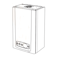
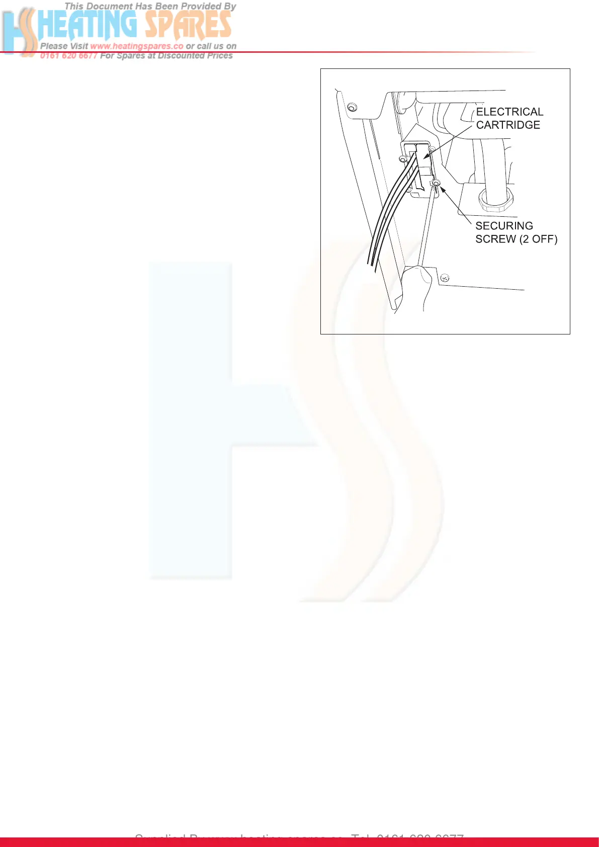
11.4 Electrical Cartridge Securing
Fit electrical cartridge into the interface housing on completion
of the wiring, see diagram 11.4.
Secure with the two cartridge retaining screws provided in the
cartridge body.
11.5 Electrical Connections - Testing
Carry out preliminary electrical system checks as below:
1. Test insulation resistance to earth of mains cables.
2. Test the earth continuity and short circuit of cables.
3. Test the polarity of the mains.
NOTE: If you require to test the appliance refer to section 14.
11 Electrical Connection
13488
Diagram 11.4
 Loading...