Supplied By www.heating spares.co Tel. 0161 620 6677
41
MODEL CO/CO2
G31 BURNER % CO2
CHECK
(case on)
9.2 to 10.2
10.0 to 11.0
24cx
30cx
0.004
0.004
10.0
10.5
+ 0.0
- 0.9
+ 0.3
- 0.7
Throttle
TURNS
12.9 LPG CONVERSION - all models
As an option, a chargeable boiler only commissioning service
can be provided by Glow-worm Service by calling telephone
No. 01773 828100.
NOTE: Steps 12.1 and 12.3 will need to be completed before
the appliance can be converted.
This conversion should only be carried out by a competent
person approved at the time by the Health and Safety
Executive.
During the conversion to Propane use of a suitable ue gas
analyser is necessary.
● The person carrying out a combustion measurement should
have been assessed as competent in the use of a ue gas
analyser and the interpretation of the results.
● The ue gas analyser used should be one meeting the re-
quirements of BS7927 or BS-EN50379-3 and be calibrated in
accordance with the analyser manufacturers’ requirements.
● Competence can be demonstrated by satisfactory comple-
tion of the CPA1 ACS assessment, which covers the use of
electronic portable combustion gas analysers in accordance
with BS 7967, parts 1 to 4.
Tools required to make the conversion are a 2mm Allen key
and an electricians screwdriver.
Having checked :
● the appliance and system have been installed in
accordance with the instructions.
● the integrity of the ue system and ue seals....
● the integrity of the appliance combustion circuit and relevant
seals....
● that all internal/external controls are calling for heat.
● the gas service isolation valve ‘F’, diagram 12.2, is open
(1) Access the gas valve.
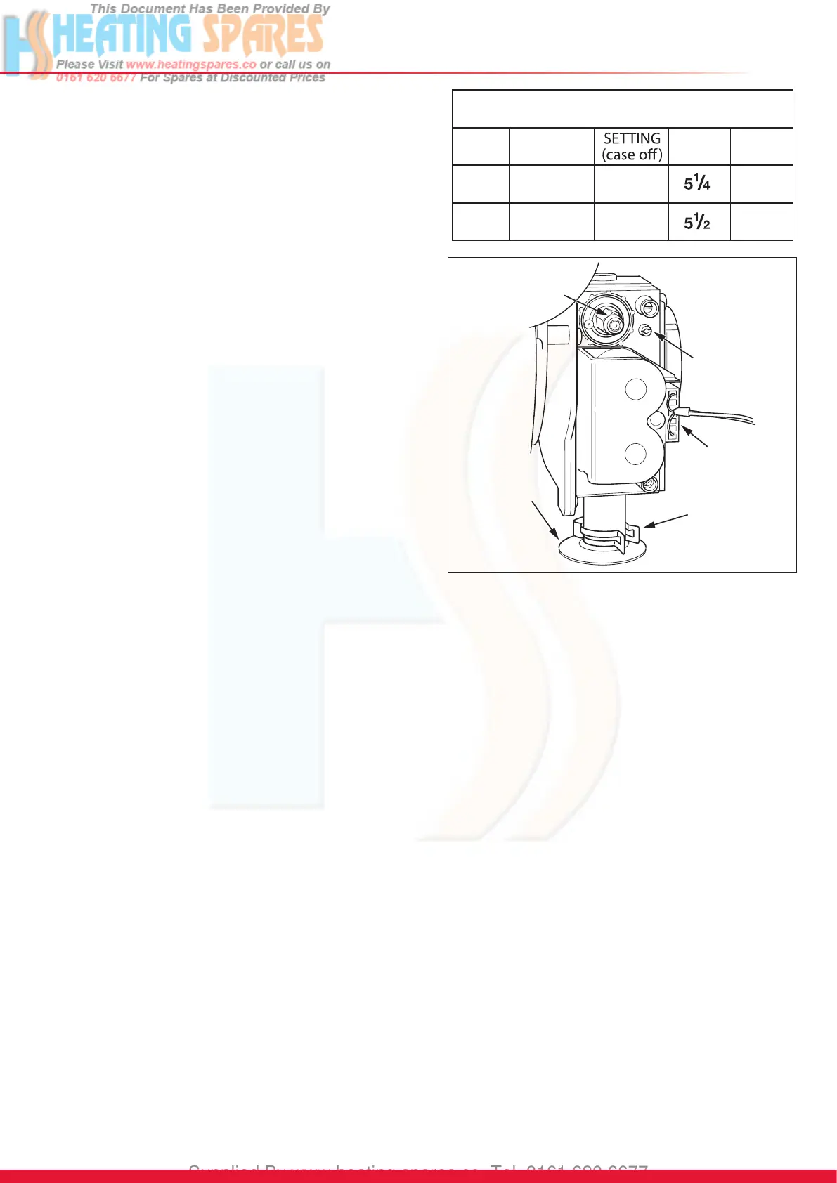
(2) Refer to diagram 12.5 and turn the gas valve throttle fully
clockwise.
(3) Turn the throttle anti-clockwise by the number of turns
shown in the table.
(4) Ensure that the gas analyser is set to the correct fuel
setting - Propane.
(5) Attach combustion analyser to the combustion test point,
refer diagram 13.1.
IMPORTANT: Remember to replace the cap on
completion of the test.
(6) Turn on the mains electrical supply and turn on the gas
service isolation valve. Switch the boiler on.
(7) Generate a hot water demand by fully opening a hot
water tap. The boiler should re automatically.
NOTE: If the appliance does not light and goes to lockout
(F1) turn the throttle anti-clockwise a further turn and
press the reset button, see diagram 12.1. The appliance
will (after a short delay) again attempt to re. Repeat this
procedure (up to a total of 2 extra turns on the throttle
screw) until the appliance lights. PLEASE NOTE several
ignition attempts may be needed, to purge gas through
the appliance, before a successful ignition is achieved.
(8) Check and adjust the burner %CO
2
at maximum rate.
Refer to diagram 12.1. Press the “reset” button on the
controls fascia, release and immediately press and hold
in the “+” button After approximately 5 seconds “Hi” will
be displayed. Pressing the mode button when “Hi” is
selected will force the boiler to maximum rate, the display
will ash between “Hi” and the “default display” this will
indicate the boiler has been forced to maximum.
(9) Adjust, if necessary, the burner % CO
2
to the value
shown in the “SETTING” column of the table, with the
throttle screw, see diagram 12.5 (rotate anti-clockwise to
increase).
Natural Gas (G20) to LPG (G31) Conversion
OFFSET
ADJUSTMENT
THROTTLE
ELECTRICA
PLUG
GAS PIPE
RETAINING
CLIP
SEALING
GROMMET
13553
Diagram 12.5
13874
(10) To exit the check sequences press the “mode” and “+”
buttons simultaneously, this will reset the boiler to the
default display.
(11) Check the burner % CO
2
, at minimum rate, to the value
shown in the “SETTING” column of the table.
(12) If adjustment is required, press the “reset” button on the
controls fascia, release and immediately press and hold
in the “+” button. After approximately 5 seconds “Hi” will
be displayed. Pressing the “+” or “-” buttons will cycle
between “Hi” and “Lo”. Pressing the mode button when
“Lo” is selected will force the boiler to minimum rate, the
display will ash between “Lo” and the “default display”
this will indicate the boiler has been forced to minimum.
(13) Adjustment of the %CO
2
is very coarse so carefully
adjust the %CO
2
to the value shown in the “SETTING”
column of the table with the offset adjustment, see
diagram 12.5 and %CO
2
Table (Rotate clockwise to
increase).
(14) To exit the function press the “mode” and “+” buttons
simultaneously, this will reset the boiler to the default
display.
(15) Repeat (8) and check CO
2
at maximum rate - adjust if
necessary. Check that the CO/CO2 ratio is less than the
value in the table above.
Please remember after nishing this procedure to turn off
the hot water tap.
(16) Remove analyser probe from the test point and replace
the cap. Ret the control panel.
(17) IMPORTANT: Fit the LPG conversion label supplied
in the documentation pack to the inner front panel
alongside the data label. Ret the inner door and
outer door.
(18) Continue commissioning from 12.5.