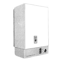
The
heater should
be
serviced
regularly
by
a
competent
person
to
ensure long
life
and efficient
use.
For
normal domcstic
installations
servicing
at
annual intervals
is
recommendcd.
Belorc
commencing a service, turn off
the
gas
and
water supplies
at
the
service
cocks,
see
diagrams
7
and 8 and
drain the
water
from the appliance
if
necessary by
rcmoval
of thc drain
screw
in
the
water
service cock,
see diagram 7 and opening
one
of
the hot
water
taps,
On
completion of
the service the drain screw
must
be
replaced
and
the appliance
checked
for
gas
and
waler soundness.
5.1
Burner
Remove
the burner
as described in Section
6.2.
After
removal the burner should be
inspected for
damage
and
any deposits
removed with
a soft
brush
or
a
vacuum
cleaner.
5.2
Pilot Assembly
Remove
the
pilot
assembly as described in
Section 6.5.
The thermocouple
should
be
removed
as
in
Secdon 6.6
its
condition
inspected.
Replace
if
necessary.
Inspect the
elecrrode for
damage.
Replace if
necessary, see Section
6.7.
The
pilot
burner
should
be
pulled
off
and inspected
for
damage and
any deposits cleaned away
with
a
soft brush.
Inspect
the injector for
deposits or
blockage
which
should
be
carefully removed and
the orifices blown
clear, see diagram 12.
Check
the
pilot
fiiter, see
Section
6.9.
After reassembly
ensure
that the elecuode
to
pilot
dimension
is
as shown
in
diagram
13
and that the
pilot
flame
strikes
the thermocouple.
Guidedimensions
are
given
in
diagram 13.
5.3
Body
For normal annual service the
body
need not
be
removed
but should be
examined and all deoosis
formed brushed
from the heat exchanger.
Remove
the
flue
hood
as described
in
Section
6.3.
Pcriodically
it may
be
necessary to remove the
body,
see Section 6.4, for descaling, the
time
interval
for
this
work
wiil
be
determincd largely
by
the
amount of usage and the hardness
of
the
water.
5.4
Diaphragm Assembly
and
Automatic
Gas
Valve
Annual servicing of this component will normally
include only
the checking of
the
diaphragm
and
regreasing
of
the
gas
valve
spindle.
BURNER
--l-_----
The spindle
may be
removed after
having
retno\'!'d
the
diaphragm
as
Section
6.
DO NOT USE
GRIPS
when
pulling
the
gas
valve
spindle
out of
is
location.
Inspect
the spindlc
for sulightncss
and
for score
marks.
If
in
any
doubt
rcncw
this
itcrtr.
Clcan
the
spindlc
carcfully
with
a soft CLEAN
cloth
and
apply
siliconc
grclsc, Dorv
Cornirts
l1 I
or
equal,
to
the spindlc.
Replace
gas valve spindlc
ensuring
that
it
moves
frccly.
If
it docs
not,
examine automatic
valve
spindle
scals
for
wear.
On
completion
of servicing
the
appliance
shotrld
bc
rc-commissioned
as
Section
4
to
check
the
opcrrttion
of
the summer/wintcr
switch,
water temperaturc
ltnd
flow
rate,
gas pressure and
thc
like.
F\i^^.am l2
uldvrqrll
l9
10

 Loading...