EasyManua.ls Logo

Glow-worm ASCOT 1.4S - Page 11

Glow-worm ASCOT 1.4S
22 pages
To Next Page IconTo Next Page
To Previous Page IconTo Previous Page
Loading...
Removal and
replacement
of
parts
must. be carried
out by
a competent
person.
Before removing
any
gas
carrying component,
turn
off
the
heater at the
gas
service
cock.
After completing the
replacement
of
gas
carrying
components,
a]ways test
for
gas
soundness
with
a
suitable
leak
detection fluid.
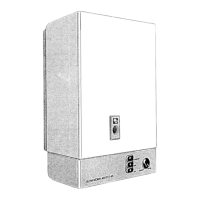
6.1
Front
Case
Remove
controls tray
by
pulling
forwards and
disengaging, see diagram
14.
Unscrew the
two securing
screws on
the
lugs at
the
bottom of
the front.
case.
Pull
bottom
of
case
forward
and
lift
the
case
up*'ards to
clear
the
retaining
brackets
on the
top
of
the main case.
The
front case
can
now
be
pull
forward
and
removed.
Reverse this
procedure
to
refit. front case ensuring
that.
case seal
is in
good
condition and
seated
correctly.
6.2 Burner
Remor,e
lhe
case
as Section 6.1.
Disconnect the ignition
lead
from
the spark
electrode,
see diagram 15.
Remove the sealing
plates
held
in
place
by
t*,o
M5
screws.
When
replacing
the
plates
care should
be
taken
to ensure that the
seal
is
correctJy
made.
\\/ithdraw
thermocouple
sufficiently to
clear
assembly
by
pulling
downwards. This
is
best
achieved
by
pulling
the
thermocouple
from
underside of base.
Disconnect
the
piiot
supply tube.
Remor.e
the cential lvl5
screw
securing
the
deflector
plate,
remove
deflector
plate
and
pilot
assembly.
Remove
the two M5
screws securing the burner
feed tube
flange
to
the uansfer elbow, see
diagram 16. Remove the
M5 scre*,
in
base,
withdraw
burner
and
burner
feed
tube
complete.
Separate the burner feed tube and
burner
by
rcmoving
the two
screws securing the
flange, then
removing
the tube.
Refit
in reverse
order,
ensuring that
both
"O"
rings
are
in
good
condition.
Renew if necessary.
Note. The
rear
of the
burner
is
located on
a
dou'el-bracket
and
it is
imporrant
to ensure
that
when
replacing
the
burner it is engaged
on
thc
dorvel-bracket.
M4
SCREW
SPARK
ELECTRO D E
M4
scREW
(2)
PII OT
ASSEM
B
LY
nr-r -^Tn6
L/trrLC\-t\Jn
PLATE
M4
NUT
(2)
M3
SCREW
IGNITION
LEAD
(CLEAR
END)
PILOT
JN I trLU
TH ERMOCO
UPLE
tvt3
SCREW
s
P ILOT
SUPPLY
TUBE
M5 SCREW
t)\
ct
s
SEALING
PLATES
Diagram
15
I
i
I
I
I
FRONT
CASE
CONTROLS
TRAY
CASING
SECURING
SCREWS
Diagram
14
>tu
11
:rl(iJ
1(i

Other manuals for Glow-worm ASCOT 1.4S

Related product manuals