EasyManua.ls Logo

Glow-worm Betacom 24c User Manual

Glow-worm Betacom 24c
68 pages
To Next Page IconTo Next Page
Page #1 background imageLoading...
Page #1 background image
Supplied By www.heating spares.co Tel. 0161 620 6677
www.glow-worm.co.uk
Installation and Servicing
High Efficiency
Condensing Combination
Boilers
Betacom
30c
G.C. No. 47-019-09
24c
G.C. No. 47-019-08
1
2
3
4
bar
0
1
0
22
21
20
19
18
17
16
15
14
13
12
11
10
9
8
7
6
5
4
3
2
1
24
23
ON
30 40 50 60 70
80 90
bar
Question and Answer IconNeed help?

Do you have a question about the Glow-worm Betacom 24c and is the answer not in the manual?

Glow-worm Betacom 24c Specifications

General IconGeneral
ModelBetacom 24c
ManufacturerGlow-worm
CategoryBoiler
Output Rating24 kW
Fuel TypeNatural Gas
DHW Flow Rate9.8 l/min
Boiler TypeCombi
MountingWall-mounted
Max. Domestic Hot Water Output24 kW
Warranty2 years
Efficiency88.9%

Summary

Safety Warnings

Gas Leak or Fault

Safety advice for gas leaks and ignition sources.

Important Information

Electrical Supply

Details on earthing, wiring regulations, and mains connection.

Statutory Requirements

GB and IE Installation Regulations

Outlines compliance with British and Irish building regulations.

Safety Devices

Servicing and Maintenance

Boiler Specification

Technical Specifications Table

Detailed technical data for Betacom 24c and 30c models.

Boiler Location, Clearances, and Ventilation

Clearances and Ventilation

Specifies minimum clearances and ventilation for safe operation.

Installation Preparation

Installation Preparation Details

Telescopic Flue - Length, Preparation and Installation

Telescopic Flue - Fitting Procedure

Telescopic Flue Fitting

Step-by-step guide for assembling and fitting the telescopic flue.

Standard Flue - Fitting Procedure

Standard Flue Fitting

Step-by-step guide for assembling and fitting the standard flue.

Vertical Flue - Length, Preparation and Installation

Twin Flue - Length, Preparation and Installation

Electrical Connection

Electrical Connection Safety

Warnings and general requirements for electrical connection.

Electrical Connection - 230V Controls and Testing

Commissioning - System Preparation

Commissioning Preliminaries

System flushing, initial checks, and gas soundness.

Filling the System

Procedure for filling the heating system and venting air.

Commissioning - Controls and Initial Lighting

Control Panel Functions

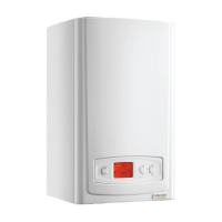
Understanding the boiler's control panel functions and settings.

Initial Boiler Lighting

Steps for initial boiler start-up and safety checks.

Commissioning - Operational Settings

Setting Operational Pressures

Adjusting minimum and maximum burner pressures for correct operation.

Commissioning - Performance Checks

Commissioning - Boiler Adjustments

Boiler Parameter Adjustments

Setting boiler parameters using potentiometers and dip switches.

Commissioning - Completion

Completion Requirements

Final checks, completing records, and handover to the user.

Instruct the User

Guidance on instructing the user on boiler operation and safety.

Commissioning - Gas Conversion

LPG Conversion Procedure

Steps for converting the boiler from Natural Gas to LPG.

Gas Conversion Settings

Minimum Setting Adjustment

Adjusting minimum burner pressure for converted gas type.

Maximum Setting Adjustment

Adjusting maximum burner pressure for converted gas type.

Servicing

General Servicing Requirements

Safety notes and general inspection points before servicing.

Competency for Combustion Checks

Requirements for personnel performing combustion measurements.

Servicing Procedures

Combustion Check and Setting Gas Valve

Checking combustion and adjusting the gas valve.

Gas Rate Check

Measuring gas rate at the meter and comparing to specification.

Routine Servicing Tasks

Steps for accessing and removing boiler panels for servicing.

Servicing - Component Access

Servicing - Component Checks and Replacement

Fault Finding

Fault Finding - Initial Checks

Preliminary Fault Finding Checks

Initial checks for electrical supply, gas, and system pressure.

Boiler Re-set Function

How to re-start a locked-out boiler.

Error Indicators and Fault Codes

Interpreting flashing indicators for boiler faults.

Fault Finding - Chart 1 (Electrical/Sensors)

Electrical Supply and Sensor Checks

Diagnostic chart for electrical supply and sensor faults.

Fault Finding - Charts 2 & 3 (DHW/CH)

Fault Finding Chart 2 (DHW)

Diagnostic chart for domestic hot water operation issues.

Fault Finding Chart 3 (CH)

Diagnostic chart for central heating operation issues.

Fault Finding - Charts 4 & 5 (DHW/CH Modulation)

Fault Finding Chart 4

Diagnostic chart for fan and air pressure switch issues.

Fault Finding Chart 5

Diagnostic chart for DHW and CH modulation faults.

Fault Finding - Chart 6 (Ignition System)

Fault Finding Chart 6

Diagnostic chart for ignition system faults.

Replacement of Parts - General

General Replacement Procedures

Safety precautions and general steps for part replacement.

Replacement of Parts - Components

Printed Circuit Board Replacement

Procedure for replacing the main printed circuit board.

Replacement of Parts - Pump and Valves

Pump Body Replacement

Detailed steps for replacing the pump body assembly.

Replacement of Parts - Sensors and Heat Exchangers

Replacement of Parts - Gas Valve

Gas Valve Replacement

Procedure for replacing the gas valve and associated connections.

Gas Valve and Combustion Checks

Checking the Gas Rate

Measuring gas rate at the meter and comparing to specification.

Checking the Combustion Products

Measuring CO/CO2 ratio and CO levels for safe combustion.

Replacement of Parts - Vessels and Thermostats

Expansion Vessel Replacement

Procedure for replacing the expansion vessel.

Replacement of Parts - Hydroblocks and Sensors

R.H. and L.H. Hydroblock Replacement

Procedure for replacing the right and left hand hydroblocks.

Manual Handling

Safe Handling and Positioning Procedures

Comprehensive guidance on safe lifting and appliance positioning.

Related product manuals