0020313973_01 Compact Installation and maintenance instructions 33
T
Flow
(target)
℃
Set maximum burner anti-cycling time
min
35 40 45 50 55 60
75 1.0 1.0 1.0 1.0 1.0 1.0
10.1.2 Setting the pump output
10.1.2.1 Pump mode setting
The product is equipped with a stage-controlled high-effi-
ciency pump. In the automatic operating mode (d.14 = 0),
the pump stage is regulated in such a way that a constantly
available pressure is guaranteed.
If required, you can manually set the pump mode to five
fixed, selectable stages based on the maximum possible out-
put. This switches the speed regulation off.
▶ To convert the pump output, change d.14 to the desired
value.
Diagnostics codes (→ Page 43)
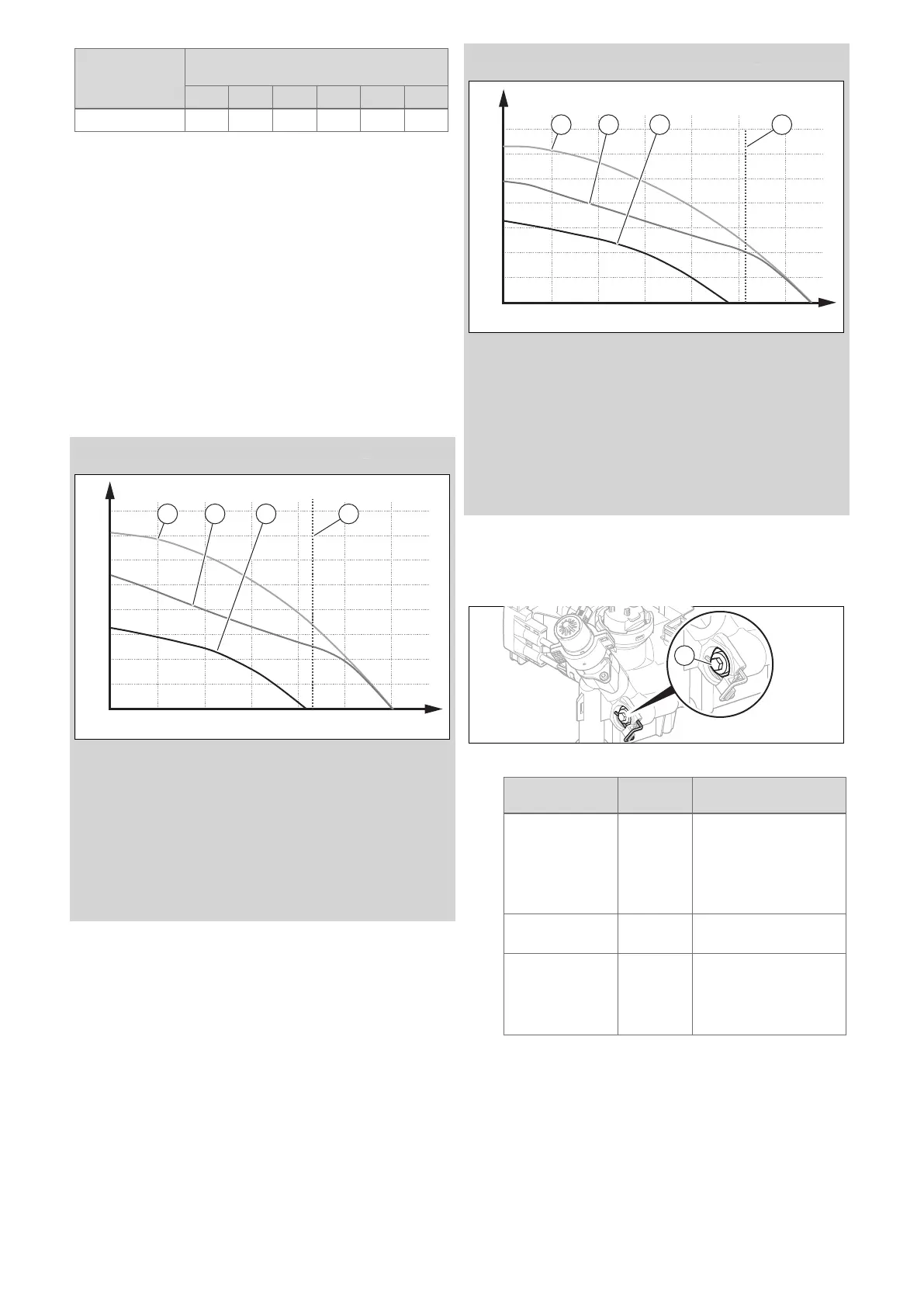
10.1.2.2 Pump diagram - pressure loss graph
Validity: Compact 24c-AS/1 (H-GB) OR Compact 24c-AS/1 (P-GB)
300
400
500
600
700
800
200
100
0
5 600400200 1000 1200800 A
B
1 2 3 4
1 Max. pump speed,
bypass valve closed
2 Max. pump speed,
bypass valve opened
by 3/4 rotation
(factory setting for the
bypass valve)
3 Min. pump speed, by-
pass valve opened by
3/4 rotation
(factory setting for the
bypass valve)
4 Qmax (ΔT = 20 °C)
A Installation volume flow
in l/h
B Remaining pump head
in hPa (mbar)
Validity: Compact 28c-AS/1 (H-GB) OR Compact 28c-AS/1 (P-GB)
300
400
500
600
700
200
100
0
5 600400200 1000 1200800 A
B
1 2 3 4
1 Max. pump speed,
bypass valve closed
2 Max. pump speed,
bypass valve opened
by 3/4 rotation
(factory setting for the
bypass valve)
3 Min. pump speed, by-
pass valve opened by
3/4 rotation
(factory setting for the
bypass valve)
4 Qmax (ΔT = 20 °C)
A Installation volume flow
in l/h
B Remaining pump head
in hPa (mbar)
10.1.3 Setting the bypass valve
1. Remove the front casing. (→ Page 19)
2. Hinge the electronics box downwards.
3. Regulate the pressure using the adjusting screw (1).
Position of the
adjusting screw
Pressure Notes/application
Right-hand stop
(turned all the
way down)
0.035 MPa
(0.350 bar)
If the radiators do not
heat up sufficiently at the
factory setting.
In this case, you must
set the pump to the
maximum speed.
3/4 revolution
anti-clockwise
0.025 MPa
(0.250 bar)
Factory setting
Three further
anti-clockwise
rotations starting
from the mid-
position
0.017 MPa
(0.170 bar)
If noises occur at radiat-
ors or radiator valves.
4. Hinge the electronics box upwards.
5. Install the front casing. (→ Page 19)
 Loading...


