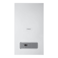
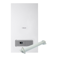
Do you have a question about the Glow-worm ENERGY 25c and is the answer not in the manual?
Classification of action-related warnings by severity of possible danger using warning signs and signal words.
Lists risks associated with unqualified personnel performing set-up, installation, maintenance, and decommissioning.
Defines the product's intended purpose as a heat generator for closed heating and hot water generation.
Safety instructions on what to do if gas is smelled in the building, emphasizing ventilation and avoiding ignition sources.
Warning about flue gas escaping into the room air if the condensate trap/siphon is not full.
Instructions on actions to take if flue gas is smelled, including ventilation and switching off the product.
Prohibits product use in storage rooms with explosive or flammable substances like petrol or paint.
Safety measures before working on the product, including unplugging and checking for voltage.
Emphasizes installing necessary safety devices and observing national/international standards.
States the product must only operate with a fully installed air/flue pipe and closed casing.
Advises carrying out work on components only after they have cooled down.
Recommends that the product be transported by at least two people.
Warns about corrosive substances in combustion air and advises separate installation rooms if needed.
Advises against installing the product in rooms prone to frost.
Recommends using the correct tool for tightening or loosening threaded connections.
Emphasizes observing national regulations, standards, guidelines, and laws for installation.
Instructs to observe all operating and installation instructions included with system components.
Advises passing instructions and documents to the system operator.
States the instructions apply only to specific product article numbers listed.
Explains Glow-worm's membership in the Benchmark Scheme for quality installation and servicing.
Notes that compartment ventilation is not required as products are certified for concentric flue systems.
Details the information found on the product's identification plate, including serial number and product type.
Identifies and labels the main functional components of the combination unit with a diagram.
Explains that the CE label indicates compliance with applicable directives as stated on the identification plate.
Provides guidance on safely lifting and transporting the unit, emphasizing it's a two-person lift.
Instructs to remove the product from its box and remove protective film from all components.
Advises checking that the scope of delivery is complete and intact against a provided list.
Presents detailed dimensional drawings of the product for installation planning.
Specifies required minimum clearances around the product for safe and efficient operation.
Instructs to use the provided mounting template to ascertain drilling locations.
Guides on checking wall capacity and using correct fixing materials for wall mounting.
Provides step-by-step instructions for removing and reinstalling the front casing of the unit.
Details the procedure for removing and installing the side section, with a caution against removing both at once.
Advises ensuring the existing gas meter can supply the required gas rate.
Covers connecting gas and water lines, including safety precautions and leak-tightness checks.
Explains how to connect the drain pipework, ensuring a continuous fall and safe discharge.
Details the installation of the condensate discharge pipe, adhering to regulations and material suitability.
Outlines requirements for electrical installation, emphasizing safety and qualified electricians.
Explains how to access and set system parameters using diagnostics codes for adaptation.
Describes how to display the product's current operating status using status codes.
Details how to activate various check programmes to trigger special functions on the product.
Specifies that initial start-up must be done by a qualified technician using a checklist.
Emphasizes checking the gas type for optimum combustion quality and routine maintenance.
Advises checking the factory gas setting against the available gas group at the installation location.
Guides on checking and treating heating water quality, including pH value and potential corrosion issues.
Details required filling pressures and actions for low water pressure situations to prevent damage.
Instructs to switch on the product via the main switch installed on-site.
Provides steps for filling and purging the heating installation, including checking connections for leaks.
Details the procedure for filling the condensate siphon with water to ensure proper function.
Outlines the process for filling the hot water circuit and checking connections for leaks.
Covers checking gas flow rate and connection pressure, emphasizing qualified personnel.
Instructs to check the gas pipe, heating circuit, and hot water circuit for leak-tightness.
Explains how to set the burner anti-cycling time to prevent frequent burner switching and save energy.
Guides on adjusting the pump output, especially when a low loss header is installed in the system.
Details how to correctly set the bypass valve for the high-efficiency pump, avoiding damage.
Warns about legionella risk and provides instructions for setting the hot water temperature safely.
Emphasizes using only enclosed original seals when replacing components.
Advises adhering to minimum inspection and maintenance intervals for product longevity.
Recommends using original spare parts for fault-free and safe operation of the product.
Details the procedure for checking the CO2 content using a check programme and analyser.
Guides on adjusting the CO2 content if it falls outside the specified range, with caution.
Provides step-by-step instructions for removing the gas-air mixture unit, including safety precautions.
Details how to clean the heat exchanger ribs with water, protecting the electronics.
Advises checking the burner surface for damage and replacing it if necessary.
Explains how to check the ignition electrode for damage, distance, and seal integrity.
Guides on cleaning the condensate siphon, including removing the float and flushing components.
Details the process for cleaning the filter in the cold water inlet without fully removing it.
Provides steps for removing and cleaning the heating filter and reassembling components.
Instructs on reinstalling the burner, seals, and gas-air mixture unit correctly.
Outlines the procedure for draining the product on the water side using check programmes.
Guides on measuring and topping up the expansion vessel's pre-charge pressure.
A reminder to check the CO2 content as part of completing maintenance work.
Instructs to check the entire product for leak-tightness after maintenance.
Directs users to appendix tables or check programmes for rectifying fault codes (F.XX).
Explains how to access the stored fault memory containing the last 10 fault codes.
Details how to delete the fault memory using a specific diagnostics code (d.94).
Guides on resetting all parameters to factory settings using diagnostics code d.96.
Lists essential steps before starting repair work, including switching off and disconnecting the product.
Introduces the section on replacing various defective components within the unit.
Step-by-step instructions for removing and installing a new burner.
Instructions for removing and installing a new gas-air mixture unit.
Details the process for removing and installing a new heat exchanger.
Provides steps for disconnecting the pump, removing the head, and installing a new one.
Guides on removing and installing a new expansion vessel, including refilling and purging.
Instructions for safely removing and installing the main PCB.
Details the procedure for removing and installing the PCB for the user interface.
Steps for removing and installing a new expansion relief valve with a new O-ring.
Guides on removing and installing a new volume flow sensor.
Instructions for removing and installing a new pressure sensor.
Final check to ensure the product is leak-tight after repairs or component replacement.
Provides an overview of available check programmes and their functions for product testing.
Lists and explains various diagnostics codes used for adapting the product to system requirements.
Summarizes the status codes that indicate the product's current operating status.
Lists fault codes, their meanings, and possible causes for troubleshooting.
Presents the wiring diagram for the Combi boiler, illustrating component connections.
Provides the specific wiring diagram for the 35 kW Combi boiler model.
Lists required inspection and maintenance tasks and their intervals.
Details the required positioning of air/flue pipe openings relative to building features.
Specifies maximum permissible lengths for different types of air/flue pipes based on diameter.
Presents detailed technical specifications for heating, domestic hot water, and general aspects.
| Output | 25 kW |
|---|---|
| Fuel Type | Natural Gas |
| Mounting | Wall-mounted |
| Efficiency Rating | A |
| ERP Rating | A |
| Central Heating Flow Temperature Range | 30-80°C |
| Warranty | 2 Years |
| Type | Combi boiler |


