Set-up 4
0020177746_03 ENERGY Installation and maintenance instructions 9
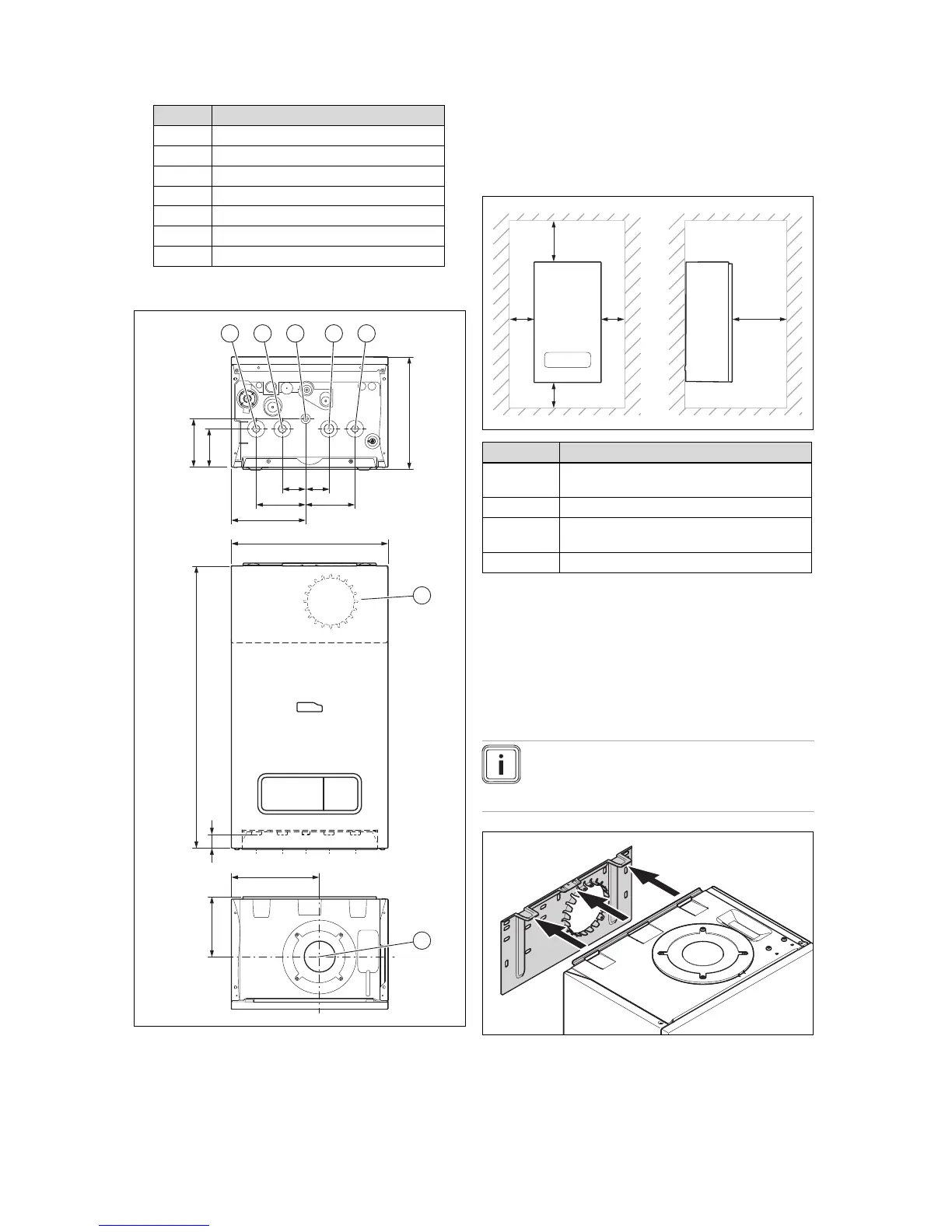
Number Designation
2 Connection pipe (heating flow and return)
1 Cold water connection pipe
1 Domestic hot water connection pipe
1 Gas pipe
1 Expansion relief valve discharge pipe
1 Mounting template
1 Enclosed documentation
4.4 Dimensions
Minimum clearance
A 150 mm (top air/flue gas connection)
20 mm (air/flue gas connection on the rear)
B 150 mm
C 5 mm
(70 mm if the side panels ought to be removed)
D 600 mm
It is not necessary to maintain a clearance between the
product and components made of combustible materials that
go beyond the minimum clearances.
4.6 Using the mounting template
▶ Use the mounting template to ascertain the locations at
which you need to drill holes.
4.7 Wall-mounting the product
Note
If you are using the rear air/flue gas connection,
install the air/flue pipe before you wall-mount the
product.
1. Check whether the wall has sufficient load-bearing ca-
pacity to bear the operational weight of the product.
2. Check if the supplied fixing material may be used for
the wall.

 Loading...

