Supplied By www.heating spares.co Tel. 0161 620 6677
10
220562A
5 L i g h t i n g , T e s t i n g a n d F i t t i n g I n t e r n a l P a r t s .
Diagram 5.6
Diagram 5.4
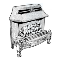
5.3 Internal Parts - Fitting
CAUTION. If the insulation, fuel effect bed base, fuel
effect bed and fuel effect pieces are damaged do not light
the fire or further test before replacement parts are fitted.
USE ONLY THE “FUEL EFFECT” APPROVED FOR
THIS FIRE FRONT.
To fit the insulation, fuel effect bed base, (pulling it
forward to fit by using the finger holes) fuel effect bed
and fuel effect pieces follow the sequence given in
diagram 5.5, 5.6, 5.8 and 5.9.
Diagram 5.7 shows the different shapes of the fuel effect
pieces and fuel effect bed.
Fit fret, see diagram 5.10.
5.4 Heat Settings
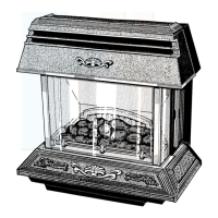
Refer to diagram 5.4.
In the unlikely event of the burner going out whilst fire
is on, turn off. Wait 3 minutes before relighting.
If relighting for any other reason, wait 2 minutes before
doing so.
LOW AND IGNITION
HIGH
PUSH IN AND TURN
ANTI-CLOCKWISE
3518
INSULATION
4016
“A” NOTE: USE FINGER HOLES
LEFT AND RIGHT TO PULL
DOWN FUEL EFFECT BED BASE
4015
FINGER
HOLE
A
FUEL EFFECT BED BASE
FUEL EFFECT BED BASE
LOCATING
BRACKET
FINGER HOLES
PULL
DOWN
Diagram 5.5
 Loading...