Supplied By www.heating spares.co Tel. 0161 620 6677
11
220562A
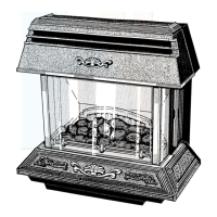
5 L i g h t i n g , T e s t i n g a n d F i t t i n g I n t e r n a l P a r t s .
Diagram 5.7
Diagram 5.8
Diagram 5.10
Diagram 5.9
Round fuel effect
pieces (2)
Oblong fuel effect
pieces (3)
Triangular fuel effect
pieces (5)
NOTE: The depressions indicate the position
of fuel effect pieces.
The 2 front fuel effect pieces have no
depressions for location.
(Dotted lines indicate positions.)
4013
Depressions
Positions for 2
front effect pieces
FUEL
EFFECT
BED
4012
FUEL
EFFECT
BED REAR
SUPPORT (2)
FUEL EFFECT
BED
FRONT
SUPPORT (2)
FUEL EFFECT
BED
4014
FRET
LOCATION
PEG (2)
Note: Take care not to damage fuel
bed and fuel when lifting the fret
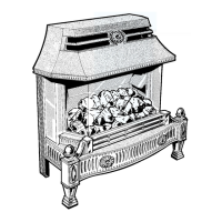
POSITION OF ROUND
FUEL EFFECT PIECES
POSITION OF ROUND AND OBLONG
FUEL EFFECT PIECES
POSITION OF ROUND OBLONG
AND TRIANGULAR FUEL
EFFECT PIECES
LOCATION
HOLE (2)
4014
 Loading...