14221788B
5 Boiler Installation
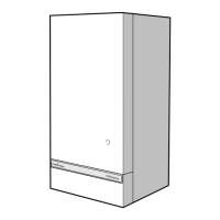
Diagram 5.4
TABLE 4.
SHORT FLUE 100-280 CUTTING LENGTHS
100-150
150-200
200-280
WALL
THICKNESS
AIR DUCT
FLUE DUCT
0 130 130 0
20 190 190 20
70 190 190 70
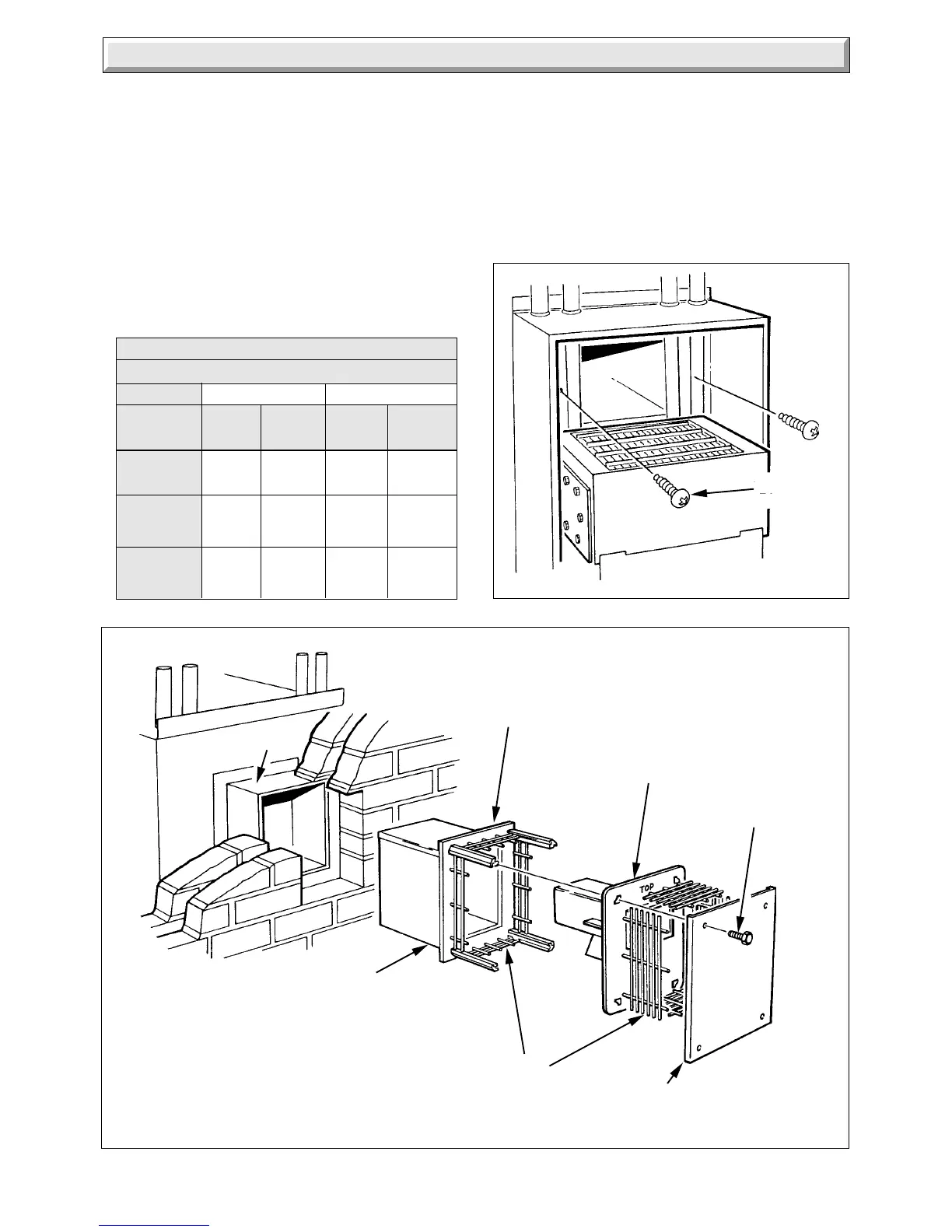
Diagram 5.3
Flue
Duct
Air
Duct
Wall
Duct
3801
3802
SECURING
SCREW (2)
WALL DUCT
WIRE
GUARDS
OUTER
BAFFLE
WALL
PLATE
SCREW (4)
INNER BAFFLE/
FLUE DUCT
ASSEMBLY
AIR DUCT
ASSEMBLY
Inner Baffle
Flue Duct
5.2 Water Circulation System
Complete the water connections to the boiler.
Fill, vent and cold flush the system as recommended in the
current issue of BS6798.
Check for any water leaks and put right.
5.3 Gas Connection
Make the gas connection to the Rc
1
/
2
in gas service cock.
Check for leaks using a suitable leak detection fluid.
5.4 Control Box
Remove the electrical control box securing screw, see diagram
5.7. Pull the control box down at the front and support on the
hook at the rear of the control box cover, see diagram 5.8.
 Loading...