22221788B
9 Fault Finding
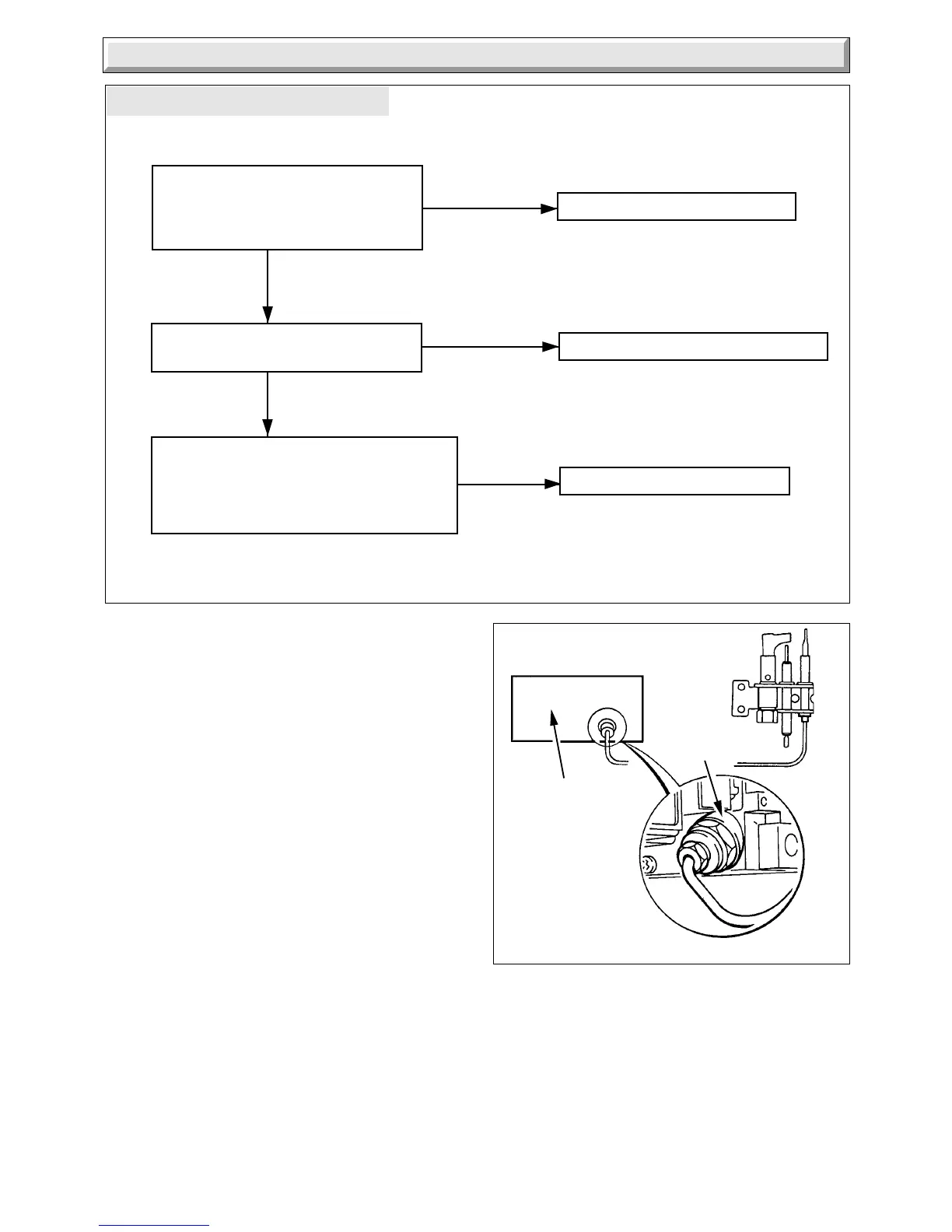
Diagram 9.2
Diagram 9.2A
THERMOCOUPLE FAULT FINDING
4634
Is the connection between the
thermocouple and the multi-functional
control clean and tight ?
See diagram 9.2A, "Connection A"
Clean contacts and re-connect
Is the pilot flame correct length?
Approxomately 12mm.
Check pilot injector and regulate pilot
Check the thermocouple output
(8-15mV, closed) or replace thermocouple.
Reference should be made to procedure 7,
British Gas Multimeter Instruction Book.
Does the pilot now stay alight ?
Change multi-functional control
YES
NO
YES
NO
NO
3816
MULTI-FUNCTIONAL
CONTROL
CONNECTION 'A'
9.1 Pilot
Refer to Chart 9.1.
9.2 Thermocouple
To test the thermocouple a meter with a range of 6 to 30mV is
required together with a thermocouple interrupter test unit.
Refer to thermocouple fault finding chart, diagram 9.2 and
diagram 9.2A.
9.3 Electrical
Important. On completion of the service/fault finding task which
has required the breaking and remaking of the electrical
connections the earth continuity, polarity, short circuit and
resistance to earth checks must be repeated, using a suitable
multimeter.
Refer to Fault Finding, Wiring and Functional Flow diagram 9.3
and 9.4.
 Loading...