42
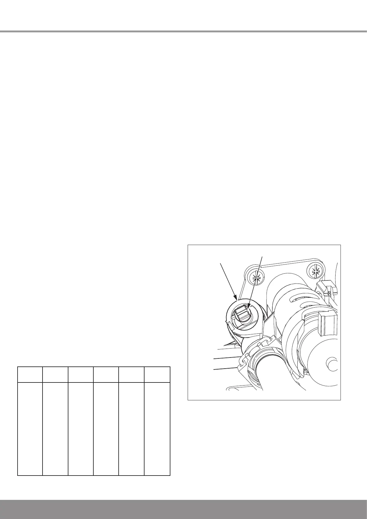
AUTOMATIC
BYPASS VALVE
BYPASS SCREW
12.5 Gas Rate
The gas valve is factory set for natural gas G20 and should need
no adjustment.
Should any doubt exist about the gas rate, check it using the
gas meter test dial and stop watch at least 10 minutes after the
burner has lit, making sure that all other gas burning appliances
and pilot lights are off.
The boilers are fully modulating for central heating, and it is
therefore not necessary to range rate the boiler.
For approximate gas rates, refer to section 1 Specification Table.
The gas valve is factory set for natural gas (G20) and should
need no adjustment. It should be checked that the supply
pressure is 20mbar when the boiler is firing at full rate. This can
be achieved by turning on several hot water taps and checking
the inlet pressure at the pressure test point on the gas service
cock, see diagram 12.1. Turn taps off and disconnect pressure
gauge.
In the unlikely event that the gas valve needs adjusting, refer to
section 13 Servicing - Combustion Check. Re-setting of the gas
valve requires a combustion analyser and any adjustment should
only be carried out by a competent person.
NOTE: The burner pressure cannot be measured at the gas valve
as it is altered by the suction of the fan and modulated according
to demand.
Testing Flue Gases: If any doubt exists that the flue products
are not exhausting correctly, investigate by use of a flue gas
analyser.
12.6 Range Rating
The boilers are fully modulating for central heating, and it is
therefore not necessary to range rate the boiler. However, if
desired, it is possible to range rate the boiler between 9 and
24kW in 1kW increments as follows:
a) Press and hold the ‘MODE’ button for 5 seconds.
The display will change to flashing ‘0’.
b) Use the ‘+’ or ‘-’ button to scroll to 96.
c) Press ‘MODE’ to confirm.
d) The display now shows a flashing ‘d.
0’. The part
load setting is displayed above in kW
e) Press ‘MODE’ to change, use the ‘+’ or ‘-’
button to change this value to the desired setting.
h) Press ‘MODE’ to confirm, the new setting has been
saved.
i) Press and hold ‘MODE’ to exit.
NOTE: For approximate gas rates at part load, refer to table
below.
12 Commissioning
13234
Diagram 12.5
12.7 Water Systems
Check that all external controls are calling for heat, the boiler
will fire automatically. Fully open all radiator valves and the
flow control valve, if fitted, see diagram 4.1.
Balance the radiators as required and if fitted adjust the valve
to give the required system differential. Turn off all radiators
that can be shut off by the user and check to see if less than
the maximum differential allowed of 20
o
C can be achieved
across flow and return.
The pump has two speeds and can be adjusted depending
on the requirements of the central heating system, see
diagram 4.2.
The boiler has an inbuilt automatic adjustable bypass valve.
The pressure can be adjusted between approx 1.5 and
3.5mH2O but is factory pre-set to approx 2.5mH2O. The
pressure changes by approx 0.1mH2O for each full turn
of the bypass screw, see diagram 12.5. Turning clockwise
increases the pressure and turning anti-clockwise decreases
the pressure.
Allow the system to reach maximum temperature then switch
off the boiler by isolating from the electrical supply.
Lock or remove the handle from the control valve, if fitted.
Adjust the boiler temperature controls and any system
controls to their required settings.
We recommend that the domestic hot water should be run for
a short period until clear.
kW m3/hr ft3/hr kW m3/hr ft3/hr
24 2.5 88.6 16 1.7 58.9
23 2.4 84.7 15 1.6 55.4
22 2.3 81.2 14 1.5 51.5
21 2.2 77.3 13 1.4 48.0
20 2.1 73.8 12 1.3 44.1
19 1.1 69.9 11 1.2 40.6
18 1.9 66.4 10 1.0 36.7
17 1.8 62.9 9 0.9 33.2

 Loading...


