DESCRIPTION EC 65
12/09 7
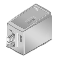
Force range adjusting
slide
The range in which the crimp die is pressed together
with full force can be set with this slide. If the die meets
with an obstruction outside this range, the crimping die
open immediately to avoid damage to the die or to the
falsely inserted material.
Position 1: min. force range
Position 5: max. force range
Positions the crimp contact and presses this together
with the wire.
It consists of the top and bottom die. These can be
changed depending on the application.
Prevents injury to fingers and hands in the danger area
of the crimp die.
The EC 65 only works when the protective cover is fully
inserted.
Serves for transporting the EC 65.
Device connection for the foot switch.
Device connection for the power cable.
Fine fuses (2x) integrated in the mains connection.
Switches on the power supply (I pressed) or off
(0 pressed). The LED on the control panel
lights up after switching on.
Pressing the foot switch triggers the crimping process.
The foot switch must be kept pressed until the crimp die
is fully closed (mode 1) or the crimp contact is clamped
(mode 2).
If the LED lights up on the control panel the
crimping process cannot be triggered.