Do you have a question about the Gmade R1 ROCK BUGGY and is the answer not in the manual?
General safety guidelines for operating the RC model.
Lists necessary RC components, batteries, and tools.
Parts for axle housing, C hubs, and knuckle arms.
Components including differential caps, gears, and shafts.
Parts for the transmission housing, motor plate, and gears.
Chassis frame, battery plate, and chassis shafts.
Includes upper/lower links, rod ends, and balls.
Bighorn tires, beadlock wheels, and rings.
Assortment of screws, nuts, washers, and rings.
Parts for building shock absorbers, including springs and oil.
Detailed steps for assembling the main axle differential.
Assembling the C Hub carrier and portal gears.
Connecting the knuckle arm and wheel axle.
Attaching front link mounts to the axle.
Assembling the rear portal gears and shafts.
Attaching rear link mounts to the chassis.
Mounting the servo and its support plate.
Connecting steering linkage rods and shafts.
Building the main chassis structure.
Installing chassis shafts for rigidity.
Assembling counter gears within the transmission.
Attaching the motor plate to the transmission housing.
Installing the center skid plate.
Installing the motor and pinion gear, adjusting mesh.
Assembling universal joints and shafts.
Building the lower and upper suspension links.
Connecting suspension links to the front axle.
Connecting suspension links to the rear axle.
Installing drive shafts to the drivetrain.
Final attachment of suspension links to the chassis.
Guide to setting up shocks for low stance and CG.
Guide to setting up shocks for rugged terrain.
Building the shock absorbers for droop setup.
Building the shock absorbers for sprung setup.
Attaching the assembled shocks to the chassis.
Cutting out and folding body panels.
Instructions for painting the polycarbonate body.
Fastening the body panels to the chassis.
Preparing and attaching body posts.
Mounting tires onto beadlock wheels.
Attaching front wheels to the axle hubs.
Attaching rear wheels to the axle hubs.
Lists axle, drivetrain, transmission, chassis, and link components.
Includes screws, nuts, shock parts, and bearings.
Lists tires, wheels, body panels, decals, and manual.
Lists essential external components needed for operation.
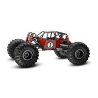
| Scale | 1/10 |
|---|---|
| Length | 440 mm |
| Wheelbase | 313mm |
| Drive Type | 4WD |
| Vehicle Type | Rock Buggy |
| Ground Clearance | 75mm |
| Body | Polycarbonate |
| ESC | Not included |
| Radio | Not included |
| Servo | Not included |
| Weight | 2.5 kg |
| Motor Type | 540 Brushed Motor |
| Battery Type | 7.2V NiMH or 2S LiPo |
| Suspension | 4-Link |
| Shock Absorbers | Oil-Filled |
| Chassis | Tube Frame |