GMT 050 User manual
8
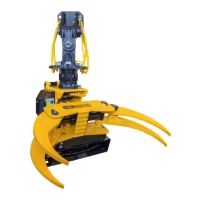
4.2 Mounting the felling grapple
Two hydraulic hoses are attached to the front side of the manifold. The long hose fitted to nipple A on
the valve block must be attached to the grapple open ( G.O. ) coupling underneath the rotator. The
short hose fitted to nipple B on the valve block must be attached to the grapple close coupling ( G.C. )
underneath the rotator.
Connection of the hoses to the manifold
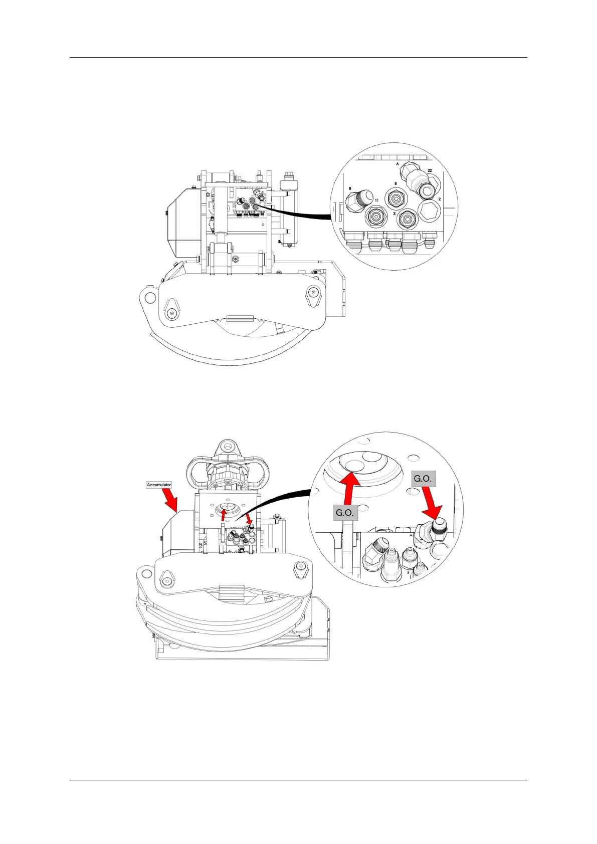
The rotator must be placed on the tilt frame in such a way that the G.O. (grapple open <>) coupling is
located on the side of the accumulator. This will mean that the G.C. (grapple close ><) coupling is
automatically located on the side of the chain oil reservoir.
Connection of the hoses to the rotator
Both hydraulic hoses must form a neat loop when attached to the nipples underneath the rotator. The
short hose must rest inside the loop created by the long hose.