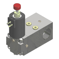
NGV A3 VALVE
INSTALLATION, USE AND MAINTENANCE
10991483 EN - 1.10 26.05.2023
NGV-A3 VX.XRXXHX
1-DIAGNOSTICS
Pressure gauge [bar] read by the pressure transducer on valve
Temperature gauge [°C] read by the temperature transducer
1.4 INPUT S0123DICA
000000000
State of the input signals: S0123DICA
1.5 Output 1234YNd
0000000
State of the output signals: 1234YND
Supply voltage [V] of the control board
Total time of the lift travel [s]
Time between the start of the lift end the start of the deceleration
phase [s]
Time between the start of the deceleration phase and the stop of the
lift [s]
Active alarms. Each alarm is identified by a code explained in the
Failure Chart. Last 8 alarms are stored in memory
- 3 - RESET ALARM AND FAULT
NGV-A3 VX.XRXXHX
3-AL/FLT RESET
3.1 Reset?
ESC=NO ENT=YES
Pressing the ENT key on the programmer all the faults and the alarms
are deleted
 Loading...