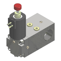
NGV A3 VALVE
INSTALLATION, USE AND MAINTENANCE
10991483 EN - 1.10 26.05.2023
Increase power voltage by adjustment or
replace power supply
Decrease power voltage by adjustment
or replace power supply
Pressure transducer PT failure
Temperature transducer TT failure
Stepping motor (SM) overheated
Wait for motor cooling.
If the problem recurs after a short time,
replace stepping motor.
Contact S1 (VRP) open with lift stopped
Contact S1 (VRP) open at the end of a
downward travel
Signals VS and D contemporaneous
Verify that the control panel sends
signals correctly
Maximum pressure > 5.10 PSTAT MAX
Verify that the parameter is equal to the
system value. If it is not equal, set
parameter equal to the system, if equal
to find the cause of overpressure.
Minimum pressure < 5.7 PSTAT MIN
Find and correct the cause that does not
allow to the pressure to reach the
minimum value required.
Minimum oil temperature < 5°C
Verify that the sensor works correctly or
install an oil heater.
Maximum oil temperature > 5.11 COOL
TEMP
If the parameter 5.11 COOL TEMP is <
70°C set the value up to 70°C
If the parameter 5.11 COOL TEMP is
= 70°C probably you must install an
heat exchanger
Contact S3 (VBO) closed with lift stopped
Verify that the sensor works correctly
placing a magnet near to its white side.
If the led does not change status (Led
not turn on if it is in off status or led not
turn off if it is in on status) the sensor is
broken and you must replace it.
If the led changes status (Led turn on if
it is in off status or led turn off if it is in
on status) the sensor works correctly.
You should try to move the sensor to the
correct position. (see 6.5). If the problem
persists on the sensor S1 probably the
VRP does not work correctly (verify
and/or contact support). If the problem
persists on the sensors S2 e S31
probably the stepping motor does not
work correctly (verify and eventually
replace) or not work correctly the VB
(verify and/or contact support)
Contact S2 (VBC) opened with lift
stopped
Contact S1 (VRP) did not opened during
starting downward travel
Contact S1 (VRP) did not closed during
end of downward travel
Contact S2 (VBC) did not closed during
end of downward travel
Contact S3 (VBO) did not closed when
VB opens
Contact S2 (VBC) did not opened when
VB opens
Contact S1 (VRP) open before starting
upward travel
Contact S1 (VRP) did not opened during
starting or in high speed
Contact S1 (VRP) did not closed during
end of upward travel
Wrong parameters map for this SW
release. Shown when [191] ≠ “xxx”
(numeric value)
Contact GMV support. It may be
necessary to replace the electronic
card with a right one or, in case of
wrong parameters map, it is
necessary to use the PT01
programmer to set the right value for
the card in use.
A NGV-A3-03 electronic card is in use
without an active serial connection to the
control panel
Contact GMV support. You experience
this issue for a wrong serial connection
between the electronic card and the
control panel or by using a standard
electronic card instead of a reduced
(serial) one.
 Loading...